Continue to Site

Welcome to our site!

Electro Tech is an online community (with over 170,000 members) who enjoy talking about and building electronic circuits, projects and gadgets. To participate you need to register. Registration is free. Click here to register now.

  • Welcome to our site! Electro Tech is an online community (with over 170,000 members) who enjoy talking about and building electronic circuits, projects and gadgets. To participate you need to register. Registration is free. Click here to register now.

HF radio/antenna switch

Status
Not open for further replies.

Suntchi

New Member
I would like to make an 8-channel antenna switch, usable only two at a time.
It should work like this:
the inputs (radio) and the outputs (antennas) are set in any combination of the 8 connectors.
For simplicity I call them C1 ... C8 (Channel 1 ... Channel 8)
Eg:
I set that the radios are [C1] and [C2] while the antennas are {C3-C8}
I want to use radio1 [C1] with antenna {C3} or with antenna {C7}, or I want to use radio2 [C2] with antenna {C3} or with antenna {C5} and so on.
But I might want to set the radios to be [C1], [C2], [C3], [C4] and they remain only for the {C5-C8} antennas.
The operating frequency should go from 1MHz up to 70MHz better if it could go up to 146MHz.
The power involved ranges from 5W up to 2KW.
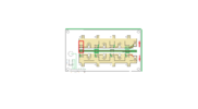
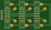
The relays that I think are suitable for this purpose are these OMRON G2RL-1-E 12V DC which have two 16A contacts in parallel. They are relays that are usually used for this purpose, in the sense that I have seen them in other antenna switches.
The connectors are from SO239 which are soldered (the central) directly to the PCB.
The connectors not in use have the central connector connected to ground.
While those in use connect the connector to the 50 Ohm track.
My problem is not only being able to calculate the sizing of the tracks but understanding how the contacts of the relays and connectors affect the overall impedance. That way I should be able to correct everything.
I am looking for some saint with great patience, able to help me and solve this problem.
 
There are commercial multi radio to multi antenna device out there already:

The biggest problem making your own is maintaining a 50 ohm impedance through the switch, and providing isolation between radios. Without enough isolation between radio ports, a radio transmitting might blow the front end of the other radio, even though it is switched out.
You may be able to figure out how to make 50 ohm stripline PCB and use reasonable relays, but isolation is even more important....
 
Hi Sagor1, all ports no in use are shorted to ground.
I have already tried using my previous PCB with 3KW power and no appreciable or rather dangerous signals enter unused radios.
I made a FR4 PCB, and I calculated the impedance with all relays and connectors mounted, but unfortunately we are not there.
I've checked impedance with both nimiVNA and nanoVNA2, but it's far from 50 Ohms, and varies a lot with frequency.
I tested the ports by putting a 50 Ohm load into the switched ports, but the SWR and RL are totally out.
Using the roger4003 (which I have never used) has a very high cost. But I would use it if I was sure I was getting a decent result.
To make the PCB I used the calculator present in Kicad.
It would be interesting to know if anyone has solved this problem and how they did it.
Thanks
 

Attachments

  • rel.png
    rel.png
    16.5 KB · Views: 200
Last edited:
The Omron relays you are considering are not designed for RF; they are often used purely as a low cost alternative for such as a single changeover (TX/RX etc.) but they are not constant impedance and using several on a bus-type system will mean you have random unterminated stubs at various points, in addition to the bus end if the last relay is not used.

Also remember the PCB tracks need to handle over 6A @ 2KW into 50 Ohms, so they cannot be too small

For short wave / HF band use, the lengths involved will be such small fractions of a wavelength that they will likely be irrelevant, but it's not something I'd want to use at VHF.

Also, the fact you are using PL259/SO239, which are not constant impedance and to be blunt generally vile connectors [face contact relying on the locking ring, rather than both inner and screen being sliding contacts], means impedance matching is not ultimately critical.


You may? get a better match in the switching part using a binary tree - eg. 1:2 then 2:4 then 4:8; three relay contacts in sequence but only ever a single signal path with no branches.
 
A long bus with relays at different points changes the impedance as the signal goes down the bus, assuming you don't have a proper match.
Commercial relay boxes often have the traces in a radial fashion (circle fan out), making each trace to each relay the same length and thus impedance is the same for each port from any common.
With multi radio input, you have to devise a "good" RF link between input relays and output relays. Not trivial to do. The more radio inputs, the more complicated it gets.
Grounding unused relays does not mean you have good isolation, especially with non-coaxial relays. Relays themselves can have poor RF isolation between contacts, even if one contact is grounded
 
Ok in the meantime, thank you and your suggestions "rienkinsgb", always welcome.
Then the coaxial relays besides costing a fortune are not suitable for this assembly, unfortunately.
Do you have any suggestions on relays best suited for this purpose?
I would say that I can stop on 50Mhz, certainly I would not use this switch either in VHF.
Unfortunately these are rules dictated by the market. HF radios use these connectors, using N or better connectors in HF is quite rare and then in any case they would require additional adapters.
The traces I calculated with the calculator present in Kicad and with the txline program of which I am attaching the results.
 

Attachments

  • Image.png
    Image.png
    30.5 KB · Views: 181
Hi "sagor1" thanks again for your support, very welcome.
Yes, I can understand that I am trying to do something unusual, but the beauty is just that, everything else is already there I would like to achieve something different. And so it seems to me very comfortable to use, too bad there are enormous difficulties in making it.
I do not ground the relays I short the port or rather the connector to which the radio is connected. I understand the fact that the relays do not have good RF isolation between the contacts, indeed I am convinced of it. But what implications can this have on operation?
 
Do you have any suggestions on relays best suited for this purpose?
I would say that I can stop on 50Mhz, certainly I would not use this switch either in VHF.
Use the Omron relays, just keep the whole thing as compact as practical, and don't be over concerned with impedance as it is totally impossible to keep that constant with that type of arrangement.

All you can do is keep the length of the discontinuities as small as you can, so it's an insignificant fraction of a wavelength.

eg. You could "fold" the line of 8 relays & connector to make two rows of four with a centre common bus.
 
Hi "rjenkinsgb", I had the same idea as you, you say you make a PCb more or less like this ?
At this point is it worth calculating the impedance of this circuit, or is it better to remove the ground below and pretend that the tracks are simple wires that connect the relays ?
Maybe by increasing their size a little so as to have a greater margin for the power in use ?
Maybe double them and connect them through vias ?
 

Attachments

  • image_2022_07_29T11_23_12_256Z.png
    image_2022_07_29T11_23_12_256Z.png
    14.9 KB · Views: 198
Yes, that's the type of setup I was thinking of.

I'd not remove the ground plane completely, but double up on the connector link tracks. The centre "bus" track can be big enough to handle the current without needing to be double sided, so the ground can be continuous between the upper and lower halves of the board.
 
Hi everyone, the new PCB has arrived and it looks like it has had a good result. The PCB has been made for the moment on FR4 and seems to have no major problems up to 59.172MHz the maximum SWR reported in all possible permutations was 1.16: 1, now I have to check the insertion losses and the insulation between the various ports not in use.
Thanks for your kind support.
 

Attachments

  • Immagine.png
    Immagine.png
    73.4 KB · Views: 188
Hi everyone, the new PCB has arrived and it looks like it has had a good result. The PCB has been made for the moment on FR4 and seems to have no major problems up to 59.172MHz the maximum SWR reported in all possible permutations was 1.16: 1, now I have to check the insertion losses and the insulation between the various ports not in use.
Thanks for your kind support.
Minor comment,

You might want to move the relay designators out from under the relays, or add designators to the connection points.

As they are now, you won't know which channel is which when the relays are installed. Yes, you can look at the picture of the board, but 5 years down the road it might be confusing.
 
Hi Designetor,
Yes, it is true, but this is only a prototype, in fact there are also no escape capacitors on the relay supplies.
The final will be appropriately modified, the desire to see the result quickly has generated the canonical errors
 
Status
Not open for further replies.

Latest threads

New Articles From Microcontroller Tips

Back
Top