Continue to Site

Welcome to our site!

Electro Tech is an online community (with over 170,000 members) who enjoy talking about and building electronic circuits, projects and gadgets. To participate you need to register. Registration is free. Click here to register now.

  • Welcome to our site! Electro Tech is an online community (with over 170,000 members) who enjoy talking about and building electronic circuits, projects and gadgets. To participate you need to register. Registration is free. Click here to register now.

help with mosfets

Status
Not open for further replies.
I bought some mosfets a long time ago and they keep blowing, im sure that i know how to use them but i havnt bought any different ones as im afraid i might blow them.

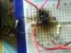
Just as a test i connected the drain to a 12v positive rail and then connected a motor to the source and then the motor to ground. I added a pull-down resistor (10k) to the gate and a diode to prevent back-emf to the motor. I connected a 1k resistor to the gate and then to a push button to +V. The motor is rated at 12v 1amp and the mosfets are P16NF06L and are rated at 60v, 16A, ±16V gate voltage.

When i press the switch the motor turns on and when i release it the motor still stays on, ive tried using pwm input to the mosfet but it still blows, or instead of a motor ive tried a resistor and the same still happens so its not the surge from the motor thats blowing them. I bought them off ebay so they could be duds.

I need to use mosfets because my application will involve high frequencies, voltages and currents, it involves a h-bridge and if one of these blows you get a good bang, bipolar transistors are too slow when they get big and give out too much heat. I can send a sample of two of these mosfets to someone like a moderator for them to test if i dont find a solution.
 
Well i suppose its medium frequency, 100-300khz.
Its a h-bridge that im making that needs to produce these frequencies, the h-bridge will be running at about 500w 60V at first, then i will go onto an igbt h-bridge running at 5kw, 320v - its for an induction heater.

I have not drawn a schematic yet, but i will post one, the whole of my setup, either in a few mins or later
 
Last edited:
You are using the Mosfet as a source-follower so its gate must be 22V for the motor to get 12V. If the motor is connected from the drain to +12V the it gets 12V when the gate gets 10V to 12V.

The gate has a high capacitance so the series 1k resistor charges it fairly slowly so it turns on fairly slowly. The 10k pull-down resistor discharges it very slowly so it turns off very slowly. High speed Mosfet circuits use a series 10 ohm resistor to prevent VHF and UHF oscillations but the gate drive current for fast switching is high.
 
induction heater end circuit.JPG
Ive attached the end part of my circuit. Its basically a half-bridge that provides high frequency, high power to the next part of the circuit. The capacitor and the inductor in series limits the current, the capacitor and inductor in parallel has a resonant frequency that has to match the input frequency in order for it to function perfectly.
This should work but i think that the problem lies with my mosfets

mosfet test.JPG

Here is my test i described in the first post, surely a 16amp mosfet shouldnt blow just running a 1amp motor like this. Note: I forgot to include the diode in the schematic to prevent back-emf.

edit: i have realised why the mosfet keeps blowing from the circuit above, but still cant understand why they are blowing in the half-bridge.
 
Last edited:
Thanks audioguru for reminding me, i totally forgot about attaching the source to 0V, i usually do that with transistors, i know that if the gate voltage exceeds the drain voltage that it may kill the mosfet, but if you look at the schematic of my half-bridge they still blow very easy even when i use the 1a motor.
Oh i also forgot to add the resistors to the gate, they should be around 100R. I keep getting mixed up a lot, im only 16 so im still learning.
 
Last edited:
i know that if the gate voltage exceeds the drain voltage that it may kill the mosfet.
No.
The gate voltage has nothing to do with the drain voltage.
The gate to source voltage must be 10V or 12V for the Mosfet to turn on. If the source is at 0V then the gate must be +10V (for an N-channel Mosfet) then the Mosfet turns on and the drain drives the load to 0V.

You had the Mosfet wired as a source-follower. Then the gate voltage must be +22V for the source to go up to the 12V drain voltage when the Mosfet turns on. But your gate voltage was only 12V so the source voltage would rise to only 2V.
 
Ah, i get you now, i think
Heres a few pictures of my setup for my induction heater.
I was running the mosfets at 30v, it was working perfectly

DSC00323.JPG

DSC00325.JPG

DSC00326.JPG

DSC00327.JPG

DSC00328.JPG

Well until i went to 60V, this happened


DSC00329.JPG

DSC00330.JPG

DSC00331.JPG

There was a lot of smoke and quite a bit of fire, i just wish it hadnt burnt my breadboard.
 
Last edited:
If you had the load connected to the source of the Mosfet like in your schematic, then the load gets only 2V when the gate voltage is 12V. Then the Mosfet has 10V across it and gets warm.
If the supply to the Mosfet is 30V then the load still gets only 2V but the Mosfet has 28V across it and gets hot.
If the supply to the Mosfet is 60V then the load still gets only 2V but the Mosfet has 58V across it and gets extremely hot.

But if the load is connected to the drain of the Mosfet then the voltage across the turned-on Mosfet is low and it does not get too hot. The load gets almost the entire supply voltage which is what is wanted.

A breadboard cannot handle the very high currents in your circuit. Of course it burned.
 
untitled..JPG

Above is basically the circuit that i made, except the voltage was 30v and most of the values were different.

Note: the schematic is not mine, its just almost the same as mine, quicker to copy it than create my own.
 
Last edited:
Your sketch of a single Mosfet is completely different to the circuit that is driven from a transformer.
 
Yes i know, when i hook up transistors i hook up the load to the +V and the collector and the emitter to ground, i usually do this with mosfets but drew that schematic without thinking.
I never knew exactly why you connect the emitter to ground or the source to ground but it all makes sense to me now.

MOSFET's don't have a collector, emitter, or base; but they do have a gate, drain, and source.
 
I know that mosfets are gate, drain and source. What i was saying is that i hooked a transistor similar to a mosfet.

Any way, i know that the problem was my mosfets and my oscillator, i think that the turn off time was too slow for the mosfets, the image below is what i could to with supplying the transformer with to drive the mosfets.
square wave for h-bridge.JPG
With this the mosfets wont be all on at once and therefore wont blow or heat up as much. The period when voltage is zero will be the mosfets turning off time. I could do with an oscilloscope the find the perfect output from my oscillator.

Any way i took some mosfets from an old inverter because i couldnt be bothered to make a new oscilator, these have a higher rating so shouldnt blow with my supply. I hooked it up to a flyback transformer from a tv, with only 6 turns on the primary. Result they didnt blow, i will still have to make a proper oscillator for when i scale it up for my induction heater.
DSC00332.JPG Plenty of heatsinks and fans to keep it cool


DSC00334.JPG
DSC00335.JPG
10mm juicy sparks because of big capacitor
DSC00338.JPG
20mm spark straight out of transformer
 

Attachments

  • DSC00330.JPG
    DSC00330.JPG
    227.5 KB · Views: 378
Last edited:
oh i know that they cant handle a great deal of current but im not using that much in this case. I could not be bothered to wait for the soldering iron to heat up so i took the risk, when i scale it up i will just use the breadboard for the control electronics. The only reason mine melted is because a mosfet blew and a resistor set on fire, it was quite cool though
 
If you gotta cool it with a fan it's way too much for a solderless breadboard. Just use soldered point to point for the high current stuff.
 
Yeah i know i should solder, i did at first with the first mosfets but as they kept blowing i got annoyed of continuously soldering them, my breadboard seems to handle high currents pretty well, ive had 5amps through it before and no problems, but i suppose it is a bad idea
 
MOSFETS 20A....30V or 60V?

I have a circuit with MTD20P03HDL which has blown. I can get a MTD20P06HDL
no problem, and wondered if someone could tell me if this would be able to be used instead. The specs look very much the same except for the Voltage.
If anyone has a Korg D1600 Schematic...it is F6 (see the image of circuit)
Summary is can I use a 60v instead of the 30V? Thank you
 

Attachments

  • Korg d1600 extract.jpg
    Korg d1600 extract.jpg
    203.5 KB · Views: 478
Status
Not open for further replies.

Latest threads

New Articles From Microcontroller Tips

Back
Top