Continue to Site

Welcome to our site!

Electro Tech is an online community (with over 170,000 members) who enjoy talking about and building electronic circuits, projects and gadgets. To participate you need to register. Registration is free. Click here to register now.

  • Welcome to our site! Electro Tech is an online community (with over 170,000 members) who enjoy talking about and building electronic circuits, projects and gadgets. To participate you need to register. Registration is free. Click here to register now.

Help with Electret Mic connection?

Status
Not open for further replies.

Ventura

Member
I need some advice about connecting a two-lead electret condenser mic (which I’m about to order) to a preamp, the final design of which is yet to be settled upon. (I have a two-transistor preamp, but I have a nice little circuit for an op-amp preamp that I may build.) Because I have a 12VDC power source available near the preamp, I’m using that to power it. (A small amount of hum is acceptable in this application.)
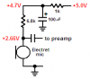
Most ECMs are rated for around 2—3VDC up to a max of 10VDC, and I understand that a current limiting resistor in series with the power is necessary…usually noted as 1k ohms or 2.2k.
The 10 volts max limit would seem to rule out my 12 volts idea. On the other hand, I read something elsewhere that says to use the higher 2.2k resistor if the voltage source exceeds 12 VDC.
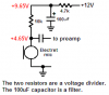
Now I’m thoroughly confused about whether or not it’s a good idea to try to use 12 volts. If it’s possible but hard on the ECM, I’d rather try to reduce the voltage to the ECM. Does a voltage divider seem reasonable in this situation? The ECM uses about .5mA. Perhaps a couple of 12k resistors in series to ground, and I could tap 6VDC from between them?

Thanks
 
Last edited:
Most electret mic operate at 0.5mA so a 10k resistor from 9V is fine.
You should use a 4.7k resistor from 12V to feed the 10k resistor with a 100uF filter capacitor to ground where the resistors join. The filter avoids motor-boating and hum.
 
audioguru said:
Most electret mic operate at 0.5mA so a 10k resistor from 9V is fine.
You should use a 4.7k resistor from 12V to feed the 10k resistor with a 100uF filter capacitor to ground where the resistors join. The filter avoids motor-boating and hum.

Hi, audioguru. I'd like to ask for a clarification of what you described, as I think I may be misunderstanding it. (Please take no offense; the shortcoming is mine.)
It sounds like you're describing a circuit beginning at 12V supply, through a 4.7k resistor, and through a 100uF capacitor to ground(?) Then connect a 10k resistor from the above resistor/capacitor junction to the ECM +lead?

I probably have this wrong. I see lots of current limiting, but no DC voltage dividing.
Thanks for your patience. Your help is much appreciated, here.

Rob
 
Ventura said:
Hi, audioguru. I'd like to ask for a clarification of what you described, as I think I may be misunderstanding it. (Please take no offense; the shortcoming is mine.)
It sounds like you're describing a circuit beginning at 12V supply, through a 4.7k resistor, and through a 100uF capacitor to ground(?) Then connect a 10k resistor from the above resistor/capacitor junction to the ECM +lead?

I probably have this wrong. I see lots of current limiting, but no DC voltage dividing.
Thanks for your patience. Your help is much appreciated, here.

No, you are correct, there's no voltage division needed.
 
The electret mic operates from a low voltage and draws about 0.5ma. So a 4.7k resistor with a 100uF capacitor is a filter for the supply to the electret mic and the 10k resistor powers it and is its load.

Of course the two resistors make a voltage divider.
 

Attachments

  • powering an electret mic.PNG
    powering an electret mic.PNG
    7.5 KB · Views: 2,542
audioguru said:
Of course the two resistors make a voltage divider.

Not really, they are just two resistors in series (with an added decoupler) - to be a voltage divider you would need to connect the bottom resistor to 0V and connect to the centre tap.
 
Nigel Goodwin said:
Not really, they are just two resistors in series (with an added decoupler) - to be a voltage divider you would need to connect the bottom resistor to 0V and connect to the centre tap.

Thank you for bringing this up, Nigel; it's been bugging me all day. I don't know a lot, but I thought I at least understood what a voltage divider is.
I've been experimenting with various resistor arrangements today, and taking measurements. What Audioguru suggested does seem to work. The voltage at the + terminal of the mic is reduced to an acceptable level. I was about to go ahead and set up the circuit that way.

But I can also drop the voltage to the mic with a voltage divider. Now I don't know what the ramifications of doing it one way or the other are. Is there a "best" way that draws the least amount of power, and holds the voltage at the mic most steady?

Thanks
 
The 4.7k resistor in my circuit allows the supply to the 10k load resistor to the mic to be filtered. Then the voltage to the mic is divided down to 4.65V (sure there is a voltage divider) which is fine.
If you want the mic to produce distortion from loud sounds then increase the 4.7k resistor to 10k so the mic gets only about 2V (sure there is a voltage divider).
 
Audioguru, you do seem to know what you're talking about and, as I said, from the bit of experimenting I did, your design seems to do what was needed. It's just that the ECM isn't connected to the resistors in what I've seen described as a "voltage divider," that is, connected between two resistances in series.
Hey, whatever works.... No offense intended.
Maybe you and Nigel will hash out what is or isn't a voltage divider....
The ECM I was messing around with today is a cheapie that someone gave me. I'm going to go ahead and order a couple of good ones and some other goodies from Digi-Key tomorrow.

Thank you, sir.
 
audioguru said:
The 4.7k resistor in my circuit allows the supply to the 10k load resistor to the mic to be filtered. Then the voltage to the mic is divided down to 4.65V (sure there is a voltage divider) which is fine.
If you want the mic to produce distortion from loud sounds then increase the 4.7k resistor to 10k so the mic gets only about 2V (sure there is a voltage divider).

It's just a load resistor, not a voltage 'divider' - one resistor (the bottom one) is the AC load resistor, and both in series is the DC load resistor.

Calling that a 'divider' is just going to completely confuse everyone.
 
Dear audioguru:

I am trying to power an electret mic from an USB port, i.e. +5V.

I am using your circuit and it seems to work properly. Nevertheless I suppose that the resistor values should better be different from the ones that you provided for Ventura, but i do not know how to calculate them.

Please, could you help me?

Best regards from spain.
 
jfmateos said:
I am trying to power an electret mic from an USB port, i.e. +5V.
When an electret mic has 5V across it then its current is about 0.5mA. With your 5V supply you need to have about half across the mic but then its voltage is lower and its current will also lower, about 0.3mA.

Ohm's Law calculates the mic's load resistor. The resistor with the lower value is used as part of the filter with the 100uF capacitor so it could be 1k. Then it has 0.3mA x 1k- 0.3V across it and the filtered voltage feeding the other resistor is 5.0V - 0.3V= 4.7V.

The mic's load resistor should have half the 4.7V across it which is 2.35V. Then its value is 2.35V/0.3mA= 7.8k which is not a standard value. Use 6.8k.

I know Nigel,
The resistors do not divide the voltage. Magic divides the voltage.:D
 

Attachments

  • powering an electret mic2.PNG
    powering an electret mic2.PNG
    5.4 KB · Views: 532
Of course the resistors act as a voltage divider, anyone with the slightest knowledge of ohm's law knows that.
 
Thank you very much audioguru, but how do you know that the current will be 0.3mA with 2.5V?

I have connected the electret MIC directly to the USB port (5V) and I only measure 0.174mA, not 0.5mA. is this measure right?
 
Last edited:
Electret mics that I have measured had a current of 0.5mA with 5V across them and a current of 0.3mA with 2.5V across them.

Every electret mic draws a slightly different current. Yours is a little lower than most but if it works then it is fine.
 
Hero999 said:
Of course the resistors act as a voltage divider, anyone with the slightest knowledge of ohm's law knows that.

????????????????

Perhaps you would like to explain how?.

Is every single collector load resistor a 'voltage divider'?, is a single bias resistor feeding the base of a transistor a 'voltage divider'?. Both are simply voltage drops across a load resistor, not a divider - exactly as the electret mike circuit.

A voltage divider requires at least two resistors, one connected to 0V, one to +ve, with the output of the divider coming from the centre tap of the two resistors - usually with a minimum of 5 times the current in the divider, that you can draw for the load.
 
Nigel Goodwin said:
????????????????

A voltage divider requires at least two resistors, one connected to 0V, one to +ve, with the output of the divider coming from the centre tap of the two resistors - usually with a minimum of 5 times the current in the divider, that you can draw for the load.

Nigel, I want to make sure I have this: In a basic two-resistor voltage divider ("top" end at +v and the "bottom" end at ground, tapped in the center to supply a load), are you saying that good (or prudent?) design usually calls for the load device to draw at least 5 times the current that the two divider resistors flow?
If the load's current draw varies, does the changing current through the "top" resistor cause the center-tap voltage to vary, in turn possibly causing unwanted effects on the load?

I guess I really should get some sort of simulator and play around with these things.

Thanks
 
The resistors act like a potential divider as far as DC is concerned. If you know the DC voltage on the microphone, then calculating the voltage across the resistors can be done using the potential divider formula.
 
Ventura said:
Nigel, I want to make sure I have this: In a basic two-resistor voltage divider ("top" end at +v and the "bottom" end at ground, tapped in the center to supply a load), are you saying that good (or prudent?) design usually calls for the load device to draw at least 5 times the current that the two divider resistors flow?
If the load's current draw varies, does the changing current through the "top" resistor cause the center-tap voltage to vary, in turn possibly causing unwanted effects on the load?
Thanks

Hi Ventura,
Just in case Nigels' gone to the pub.:rolleyes:

He is saying, 5 times more current flows in the divider resistors R1 and R2.
The load path draws about 1/5th of the divider current.

In this way any small change in load current demand has a reduced effect on the R1, R2 junction voltage.
 
Ahhh, OK, Eric. That's how I thought it should be. I wasn't sure if I correctly understood Nigel's description. Apparently I didn't. I'm glad I asked.

Slowly the light of understanding breaks through the fog of my ignorance. I'll keep slugging away at it.

Thank you
 
Status
Not open for further replies.

New Articles From Microcontroller Tips

Back
Top