Hi all,
This is my first post though occassionally I read most interesting posts.
I need to build a 1-35Amp (max voltage 35v) constant current source for Anodising Alluminium purposes. I have experimented with PWM on the DC side etc but on small loads <0.5R the circuits did not give adeqaute results.
Now I am trying to use an induvtive type dimmer and add feedback to control current in the load.
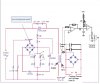
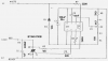
I have found a circuit (attached) from ST datasheets that looks interesting. (www.st.com/stonline/products/literature/an/3566.pdf )
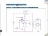
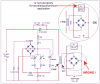
However I need some help in reading the circuit. It is a Power variation circuit for arc welding transformer using Pulse train to trigger Triac. Particularly I cannot figure out how the bridge in the primary side is configured???
Any help is welcome. I am an electronics tech specialising in TV repairs.
thanks.
This is my first post though occassionally I read most interesting posts.
I need to build a 1-35Amp (max voltage 35v) constant current source for Anodising Alluminium purposes. I have experimented with PWM on the DC side etc but on small loads <0.5R the circuits did not give adeqaute results.
Now I am trying to use an induvtive type dimmer and add feedback to control current in the load.
I have found a circuit (attached) from ST datasheets that looks interesting. (www.st.com/stonline/products/literature/an/3566.pdf )
However I need some help in reading the circuit. It is a Power variation circuit for arc welding transformer using Pulse train to trigger Triac. Particularly I cannot figure out how the bridge in the primary side is configured???
Any help is welcome. I am an electronics tech specialising in TV repairs.
thanks.
")