You turn back your clock to about 1951 and test the tubes at your local convenience store. They sold cigarettes and vacuum tubes.how do i know if the tubes are ok or not?
Continue to Site
Follow along with the video below to see how to install our site as a web app on your home screen.
Note: This feature may not be available in some browsers.
You turn back your clock to about 1951 and test the tubes at your local convenience store. They sold cigarettes and vacuum tubes.how do i know if the tubes are ok or not?
If you're using the original circuit you posted, then (like we told you) it's rubbish.
Add the decoupling components as shown in the two diagrams I posted, R5, R6, C1A and C1B in the second of the diagrams - without them you're just feeding hum from the PSU directly to the grids of the valves.
i wouldn't say it's rubbish... it's just a basic amplifier circuit...

what i need is to get rid the noise and i'm happy with it.
can you tell me how i'm going to implement your above advice? because the only thing i managed to do is to ground my signal.
Is the metal chassis connected to power supply minus (like it should be)?
Do you have a light dimmer in use? Your audio file sounds like a buzz to me. Not 50 or 100 hertz...unless severe clipping is causing me to hear only harmonics.
Pull the first tube out of the circuit and see if all the noise goes away, please.
Look at the circuits I posted earlier, and the decoupling components between the HT rail and the triode anodes - these are absolutely essential.
LM3875 etc... and he has also made an tube amp like mine but he doesn't makes any complaints about noises...nigel i did that and i only manage to ground my input signal....
i did it as is in the circuit... 10K resistors in series with 22uF/400V decoupling capacitors and then the resistors of my circuit.
probably i did wrong with the values of the first resistors?!
btw Nigel.... this guy sells some pretty good amp kits like the discontinued from national
Mikkel Corydon Simonsens hjemmeside
as i said i only want to get rid of the noises...and i'm satisfied with the amp...i knew from the start that it has lower output power (though it's NOT so low as you might think!)
the only thing i didn't knew is the very high distortion from the middle of the volume control and after....but it's OK for what i'm going to use it with.
I don't know what you mean?, try posting the circuit as you modified it.
He won't get the problem you have, he has the required components - see the 2K and 50uF to the 2nd triode, and 16K and 16uF to the 1st triode.
but both are similar with mine.If it's very high distortion, it's probably becuase you're over driving it - bear in mind it's a guitar amp, you could leave off the first stage to just feed an MP3 player to it.
first time i only connected the 22uF/400V decoupling capacitors without the 10K resistors and although the noise dissapeared.. i also lost the input signal and i understood that i was filtering the amplified output signal from the tube, second time i also used th 10K resistors but it was the same result as above.
so probably it didn't worked or maybe i did something wrong (?)
i wasn't talkin for the amp with the 6SN7 triodes i was talking about the other with the ECC82 and the EL84
btw mikkel says these words to his site about his simple design with the 6SN7 which is so similar with mine:
"The amp actually sounds fine without feedback, but the bass is a bit "boomy".
explain this to me... in case i want to connect an mp3 player i should leave the first triode outside and feed the mp3 directly to the control grid of the second triode? (ofc i'm going to use a resistor in parallel in the input)
is that right?
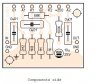
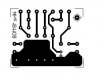
here's the pcb and the component side.... perhaps there's also an error somewhere there and i couldn't see it?
Just as a matter of interest, why did you make a PCB for it? - it's not a particularly useful method for a valve amp, especially a home made one.
Here's the layout details for the second circuit I posted, that used a double triode
i didn't wanted any pcbs i wanted it to be with the old fashioned way... but the problem with the hum made me to use a pcb.
so... i'm going to try again the capacitors to the anodes... and i'm also going to order a 5H/500mA power choke from the shop that did my transformers
i don't know if you agree with the last one.
also could you please help me with the values of the resistors for the anodes-cathodes? i want the tubes to work on normal voltages... and i can't because the schematic is calculated for 250VDC and PSU gives 310VDC.
right now for the triodes i'm using 100K for the anode and 1K for the cathode on both of them...which is not right because i lost the ratio of the original schematic and the EL84 has two 87ohm/2W resistors with a 22uF capacitor in parallel...
right now the el84 has anode 245V and it's still very high
P.S the schematic especially the layout you posted are very useful to me
because i can take ideas for the orientation of the components without using a pcb and in case one day i want to move on to a different design...but still you haven't told me if i can easily substitute the tubes of your designs with the tubes i already have or if it needs many modifications.
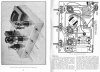
). here's the results and also some photos.ok! so heres what...
my first tube amplifier is almost ready!!
I managed to suppress the noise a bit and now it works better than ever!
but i still have 1-2 things that i want to talk about and find a solution
but these later because now i have something to show you all!
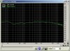
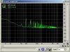
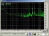
it might be pointless but out of curiocity i got this amp analysed!
Noise level dBA: -75.9
Dynamic Range dBA: 59.5
Total Harmonic Distortion THD: 59.912%
i think the numbers don't go so well, but to the ear is kinda different...
any comments?
The distortion figure will include the hum as well, did you fit the decoupling components as suggested? - they should pretty well get rid of it all, not just partially.
well no.. i did some other things first... but i'm about to do it.
as i said before i got 1-2 things to ask, first the plate of the EL84 turns a bit
red!!! (screen voltage is at 220V and anode at 245V and i don't know what causes it.)
Then the input... if i let it floating the amp get's noisy!!! (the input resistor is 1M).
as far as i know the first is because of overvoltage either to the screen or to the anode... but as far as i can tell my voltages are normal!!! if you imagine that some guys work these tubes single ended at 370V and 17W output.
and with very small screen resistors!
So you still have masses of hum, this will be added to the distortion reading (because it's distortion AND noise)
Probably too much current, increase the value of the cathode resistor to increase the grid bias on it.?).
I'm presuming you've got no positive voltage on the grid?
increasing the cathode resistor i'm also increasing anode voltage...
what do you mean with that?
When all the problems finaly get solved i'm thinking to make my amp work with High input and with low input so i can use it depending what i want to connect.
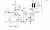
here's an updated schematic which i'm currently using and works only with the 1/2 of the ECC83
and as far