Continue to Site

Welcome to our site!

Electro Tech is an online community (with over 170,000 members) who enjoy talking about and building electronic circuits, projects and gadgets. To participate you need to register. Registration is free. Click here to register now.

  • Welcome to our site! Electro Tech is an online community (with over 170,000 members) who enjoy talking about and building electronic circuits, projects and gadgets. To participate you need to register. Registration is free. Click here to register now.

Help reading circuit?

Status
Not open for further replies.

Mishael

Member
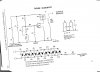
i have a circuit and i know all of the components, but i dont know how they all assemble together. im normally an abstract thinker but when it comes to these diagrams, im completely linear. i need to see what order they go in without all the jumble'd-ness
could someone just use the acronyms and terms with an order of connection like xX->xY->yX etc or something like that?

ALSO dont judge the diagram
 

Attachments

  • 1233.jpg
    1233.jpg
    485.9 KB · Views: 318
What do you mean by acronym?! Is it the Cockcroft Walton multiplier or the transformer circuit that you dont understand? The connections are made everywhere there is a black dot where the components meet. This is a stunningly simple circuit to build. Please be more clear as to what you would like help with.
 
Translating that drawing into, "connect the cathode of the first diode to one side of the first capacitor and the anode of the first diode to the cathode of the second diode..." would require a whole book. Schematics were invented because they tell so much information so simply.
 
Schematics are normally drawn left to right and top to bottom. So, look in the top left corner for the first active component; that will be the first stage. All of the passive components around it support that stage so Q1 is the first stage and everything to the left of R something (looks like a 7 but is probably a 4) is part of that stage.

By the way, this thing is an oscillator feeding a capacitive voltage multiplier.
 
Maybe he is considering the effects of working with a high voltage circuit. Circuit elements must have a minimum spacing between each other.
I too wonder if designing such a circuit brings some limitations or not.
 
The biggest limitations are the current, the sizes of the capacitors and time. It takes a cycle for each capacitor to charge and the current available at the output is low. Capacitors C5 and C6 have to be 6 times as large as C15 and C16 for this to operate at maximum efficiency. Otherwise the available output current will be starved by the undersized stage.
 
What do you mean by acronym?! Is it the Cockcroft Walton multiplier or the transformer circuit that you dont understand? The connections are made everywhere there is a black dot where the components meet. This is a stunningly simple circuit to build. Please be more clear as to what you would like help with.
I know where the connections are made but how are they made is my question. If there is a black dot mid segment does that mean that it’s similar to a T? acronyms because I had a lack of a better word for R1, C1, et cetera.

Translating that drawing into, "connect the cathode of the first diode to one side of the first capacitor and the anode of the first diode to the cathode of the second diode..." would require a whole book. Schematics were invented because they tell so much information so simply.
Im not asking for that. I don’t want words I just need something like its series connection: C1->R2->T1->R12->… and so forth
My main issue is how the diodes and capacitors are connected together

Schematics are normally drawn left to right and top to bottom. So, look in the top left corner for the first active component; that will be the first stage. All of the passive components around it support that stage so Q1 is the first stage and everything to the left of R something (looks like a 7 but is probably a 4) is part of that stage.
I sort of understand now but im still missing something. An active component is what like a battery? I know passives are resistors and such but what is active?

What don't you understand the symbols?

Look them up on Google
electronic symbols - Google Search
its not that i dont understand them, i just dont know how they connect together.
 
As has been stated, you connect them together wherever they are connected on the schematic. There is no particular order to the connections, it's just determined by what's convenient for the physical layout. The physical layout can be completely different from the schematic since you normally lay it out to try to minimize connection length between parts. It may help to draw all the components and then draw lines between them, per the schematic, for the connections. You may then realize you have to rearrange the components for the best connection layout. It generally is an iterative process.

Active components are transistors, diodes, integrated circuits, etc.
 
Last edited:
its not that i dont understand them, i just dont know how they connect together.

What are you finding difficult?

Which pin goes to what can be found on the datasheet which can normally be found by Googling the part number.

Here's a site with some information on assembling projects.
Welcome to the Electronics Club

Here's an example showing how electronic components relate to a schematic. The left is a schematic, the right picture of the components wired up.

**broken link removed** **broken link removed**
 
There are many ways to make a connection. In this circuit it isnt really critical how you do it. In something like an RF (radio frequency) circuit, it is VERY important how you position components and make connections, etc.

Your circuit can be made on a breadboard, on a pre-perforated board with point to point connections, wire wrapping, "dead bug" style, printed circuit board, etc. These are all common methods of prototyping. Here is a nice example of the COCKcroft-Walton section using the "dead bug" style, which may be easiest for the Cockcroft-Walton section because of its size:
**broken link removed** Here, the capacitors are on the bottom, upside down, and the diodes are the black cylinders on top. Note that the direction of a diode is always very important: the silver band on these diodes indicate their cathodes ( cathode --l<-- anode ). Everything is soldered with little blobs where the connections are to be made. As you can see, this example just happens to resemble what the schematic looks like, which isnt generally the case with most circuits.

With any method you choose, the angle of the connection it is not important at all - it does not have to make a "T." Although, in some high voltage or high frequency circuits, sharp angles in PCB traces can be a problem, but thats a complicated subject... In most simple stuff, like this, you dont have worry about it.

An "active component" is one which requires power to operate. Diodes, transistors, IC's, motors, etc. all require power to do their thing.
 
Last edited:
I sort of understand now but im still missing something. An active component is what like a battery? I know passives are resistors and such but what is active?
Active components are amplifiers and there are three categories, Transconductance amplifiers, transresistance amplifiers and negative resistance amplifiers. That includes transistors, vacuum tubes and other solid state devices except for most diodes.
 
Status
Not open for further replies.

Latest threads

New Articles From Microcontroller Tips

Back
Top