Hi, I'm a novice with Electronics.
I'm working on a pcb repair. The (old) board has worked great for a year. It's slowly been getting more and more difficult over a time... takes a few goes to get it to boot up. Now it won't boot at all.
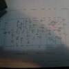
I've checked clocks, bus lines and now I'm looking at the reset circuit for clues. It does pop out of reset but instantly goes back in a cycle.
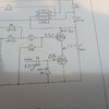
I'm looking at what the trigger is. Seems it can be the software (tr2) or 12v unregulated at 100hz (tr3). I'm measuring 10.5v from the psu on this line. It goes through c6 (10nf cermaic) and comes out at 0.2v to the base of TR3 (ztx450 npn). I don't understand how this can 'turn on' this transistor?
The last paragraph explains that tr2 and tr3 which are linked emitter to collector respectively need to be switched on to drain to ground to stop a cap charging to keep the system out reset
I'm working on a pcb repair. The (old) board has worked great for a year. It's slowly been getting more and more difficult over a time... takes a few goes to get it to boot up. Now it won't boot at all.
I've checked clocks, bus lines and now I'm looking at the reset circuit for clues. It does pop out of reset but instantly goes back in a cycle.
I'm looking at what the trigger is. Seems it can be the software (tr2) or 12v unregulated at 100hz (tr3). I'm measuring 10.5v from the psu on this line. It goes through c6 (10nf cermaic) and comes out at 0.2v to the base of TR3 (ztx450 npn). I don't understand how this can 'turn on' this transistor?
The last paragraph explains that tr2 and tr3 which are linked emitter to collector respectively need to be switched on to drain to ground to stop a cap charging to keep the system out reset