So, ultimately, depending on the current loop orientation I define, that dictates how the polarity changes in response (with respect to the voltage source). Which, in other words, determines whether the voltage term is either positive (voltage drop), or negative (voltage rise). I'm so used to having the voltage term isolated from the rest of the other terms when doing mesh-current analysis that I've forgotten how it's interpreted when included with the other terms (or simply having the loop equation be 0 = voltage term + ....). And so with that, the way current runs through resistors and sources are different that care has to be taken when arranging them correctly. Sounds like I need to take some time tonight to review passive sign orientation with sources and mesh-current analysis, since both play a role on how current runs through inductors and capacitors as well.
Yeah. You can define whatever damn current loop directions you want. As long as you stay consistent with the currents and voltage drops polarities according to your convention it when tracing your current loop in your chosen direction to write out the loop equations. You can pre-separate the sources to one side if you really want to, but you need to be aware of how it works because what happens if you get a circuit where a single current loop has two sources in it that may or may not oppose each other? Then you're screwed. Or even worse, if they're dependent sources.
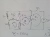
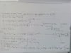
RLC mesh gets pretty ugly though if you stick to time domain. Solving differential equations due to all the inductor di/dT terms and dV/dT capacitor terms. I normally just go with frequency domain jwL and 1/jwC and then Laplace to turn it back into time domain or whatever. both are pretty involved for exam questions though if they want you to go all the way through the problem. But you still need to know it in case they just ask for a precursory analysis where an inductor or cap was already charging and a switch changes state which causes the inductor and cap to become a source. Either way, mesh analysis rides on that passive sign convention so you should know it.
Yeah...that's the term...passive sign convention. I had totally forgotten it was a thing.
Last edited: