Continue to Site

Welcome to our site!

Electro Tech is an online community (with over 170,000 members) who enjoy talking about and building electronic circuits, projects and gadgets. To participate you need to register. Registration is free. Click here to register now.

  • Welcome to our site! Electro Tech is an online community (with over 170,000 members) who enjoy talking about and building electronic circuits, projects and gadgets. To participate you need to register. Registration is free. Click here to register now.

Help on finding Thevenin Resistance and Current across resistor for RL Circuit?

Status
Not open for further replies.

Escaypism

New Member
Hello! Good evening to you all! I'm currently brushing up on RC & RL circuits in preparation for an upcoming exam, and I found this circuit to be rather complex in its design. I've had a limited understanding of natural and step responses for RC & RL circuits, and this circuit certainly hits it home. I'm supposed to find both the time constant and the current, i3(t), across the R3 resistor. My understanding of the the circuit is that for t < 0 and t = infinity, the inductor acts as a short circuit under DC conditions. However, between that, the inductor has voltage and current changing across time, so it does not act as a short circuit at t=0 or t>0.
201812030123421000.jpg

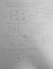
So when I attempted to find the thevenin resistance, Req, for t > 0, I recognized that the current source is removed, whilst the voltage source is a wire. However, I don't know if this is true or not, but deactivating V1 allows a connection from the right end of the inductor to the junction between R1 and R4. Such that as the inductor is discharging, some current will flow through it, suggesting that R1 and R4 are not in series. Is this is correct, then would it be safe to presume that, from the perspective of the inductor, R3 is parallel to the series combination of R4 & R5? I'm not sure how the equivalent resistance can be found, based on how the inductor is positioned inside the RL circuit.

As for finding the current i3(t), it is mt understanding that a general solution is usually used with respect to step/natural responses for RC & RL circuits: \[ i(t)\;=\;i(t=\infty\;,\;or\;0+)\;+\;\lbrack i(t=0)\;-\;i(t=\infty\;,\;or\;0+)\rbrack\ast e^{-\frac t{L/R}} \]

From this, I am under the assumption that this "could" be used to find i3(t). However, what I'm confused about is on what happens to the circuit at t > 0 and t = 0 (or t < 0). I know that the current source is disregarded for both t < 0. However, when the switch is closed at t=0, I'm not sure how this changes the original circuit diagram. I'm also uncertain as to whether I should find the current across the inductor, iL(t), first, before solving for i3(t).

I included an attachment of the attempts I've made so far, but I believe that I'm still approaching finding the equivalent resistance in the wrong way. Can someone help guide me through on how to tackle this kind of problem? Despite watching Youtube videos and referencing my textbook for problems related to this, I'e struggled with this for almost 5 hours nonstop and finally sought to ask for some much needed help. Thank you all.
 

Attachments

  • New Document_0.jpg
    New Document_0.jpg
    516.3 KB · Views: 245
Inductor does not short circuit at t>0. It short circuits after a "long time" in some operating state.

For (2):

You use superposition. One version of the circuit with current source off (aka 0 amps, open-circuit), and technically switch is closed too since t>0 is what you want, but the effect is redundant in the case of this circuit. Since the one remaining voltage source has no switch to control it, it has to have been operating as such for a long time. Therefore it is in steady state so use inductor = short-circuit = 0V. In this circuit, this just so happens to be similar, but not the same as a DC analysis.

Then make a second ersion of the circuit where voltage source is now off (aka 0V, short-circuit), and again with switch just closed. The inductor must be present here due to the activity of the switch connecting the current source producing transient (non-steady state) behaviour. In this circuit, this just so happens to be similar, but not the same as an AC analysis.

Find i3 in both versions and add them together. In this circuit, this just so happens to be sort of like finding the DC part and AC part separately and adding them together,

Or just use mesh analysis with Z = jwL for the inductor) then use Laplace to convert to the time domain.

Not sure about (1) tbh. Are they just asking you to find the equation for IL and then pull the time constant out of it? Might be a faster way to do it though.
 
Last edited:
Oh, I think I know how to do (1) now. Much faster than what I said at the end of my previous post and it makes sense now why they asked it as the first problem since it's so simple.

In my last post, I keep saying different parts of the superposition are like an AC or DC analysis due to the activity of the switch and the sources it connects or doesn't disconnect. But for (1), you do an actual AC analysis. For superposition in (2), you turned off one source at a time. But for the AC analysis, you turn of ALL DC sources off (Voltage source become shorts and current sources become open). As it so happens, all your sources are DC so they all turn off. Switch just closed as well since t > 0 is of interest.

Then you simplify it down to a super simple RL circuit and calculate the RL time constant from the two remaining component values.

tau = 1uH / 1.59 ohms

I am pretty sure this is valid. At least for the time constant when voltage source was already running and the switch closes (not necessarily for starting up the voltage source, I'm not sure).

I feel like this can be used to skip a bunch of steps to solve (2) somehow.

EDIT: Ah, yeah I think you can. You can calculate I3 in steady state conditions (inductor shorts) before the switch opens, and then again in steady state after the switch opens. Then you know the initial conditions, final conditions, and tau which tells you how the circuit gets between the two so you can put them all together in your i(t) formula in your first post.
 
Last edited:
Hey dknguyen,

I do follow your line of reasoning, based on the two posts, as to how the presence of the voltage/current sources changes in correspondence with the activity of switch. Your last thought spoke true to me, especially since the steady states are what I was also focusing as well. But based on the AC and DC situations that you described, if I understand it right, i3(t<0) can be found by having the inductor short-circuited and the voltage source present such that we can simplify the circuit into a single loop that contains the voltage source, short-circuit, and the equivalent resistance, right? (For the AC case, in which the switch is opened?)

Then, with the DC case (t>0), because the switch is closed, both current and voltage sources are ignored, but the inductor is a short circuit for t = infinity, but not for t>0. So should I ignore the t>0 situation then and only focus on the t = infinity as being the steady state, to solve for i3(t = infinity)?

Also, for the equivalent resistance that you found, I did try finding it for the case where t>0, with the sources off, with R3 in parallel with (R4 + R5) and R1 & R2 being in series with that, but I ended up with Req = 9.71. How exactly did you end up with an equivalent resistance = 1.59 ohms?

Oh, I think I know how to do (1) now. Much faster than what I said at the end of my previous post and it makes sense now why they asked it as the first problem since it's so simple.

In my last post, I keep saying different parts of the superposition are like an AC or DC analysis due to the activity of the switch and the sources it connects or doesn't disconnect. But for (1), you do an actual AC analysis. For superposition in (2), you turned off one source at a time. But for the AC analysis, you turn of ALL DC sources off (Voltage source become shorts and current sources become open). As it so happens, all your sources are DC so they all turn off. Switch just closed as well since t > 0 is of interest.

Then you simplify it down to a super simple RL circuit and calculate the RL time constant from the two remaining component values.

tau = 1uH / 1.59 ohms

I am pretty sure this is valid. At least for the time constant when voltage source was already running and the switch closes (not necessarily for starting up the voltage source, I'm not sure).

I feel like this can be used to skip a bunch of steps to solve (2) somehow.

EDIT: Ah, yeah I think you can. You can calculate I3 in steady state conditions (inductor shorts) before the switch opens, and then again in steady state after the switch opens. Then you know the initial conditions, final conditions, and tau which tells you how the circuit gets between the two so you can put them all together in your i(t) formula in your first post.
 
Also, for the equivalent resistance that you found, I did try finding it for the case where t>0, with the sources off, with R3 in parallel with (R4 + R5) and R1 & R2 being in series with that, but I ended up with Req = 9.71. How exactly did you end up with an equivalent resistance = 1.59 ohms?

R1 and R2 are NOT in series with "that".

V1 shorted so R3||(R4 + R5)

R3||(R4 + R5) is in series with R6, so [R3||(R4 + R5)] + R6

That last entire thing is in parallel with R1.

Or, put in visual terms...R4, R5, and R3 all collapse down into one resistor located where R3 (we will call it R3 prime) used to be. Then (R3 prime + R2) is in parallel with R1 which is in parallel with L1.

Hey dknguyen,

I do follow your line of reasoning, based on the two posts, as to how the presence of the voltage/current sources changes in correspondence with the activity of switch. Your last thought spoke true to me, especially since the steady states are what I was also focusing as well. But based on the AC and DC situations that you described, if I understand it right, i3(t<0) can be found by having the inductor short-circuited and the voltage source present such that we can simplify the circuit into a single loop that contains the voltage source, short-circuit, and the equivalent resistance, right? (For the AC case, in which the switch is opened?)

Then, with the DC case (t>0), because the switch is closed, both current and voltage sources are ignored, but the inductor is a short circuit for t = infinity, but not for t>0. So should I ignore the t>0 situation then and only focus on the t = infinity as being the steady state, to solve for i3(t = infinity)?

I assume you are talking about calculating the steady states at T < 0 and T = infinite, and then drop them into an equation and use tau to stitch them together?

Forget the my calling things "AC" and "DC" with regards to (2). It was just a crude visualization of superposition but it's not true since you can also operate in steady state with an AC source. Let's call them what they really are: steady state at T <0 and steady state at T = infinite.

The red text is incorrect, though maybe you just misspoke. You aren't ignoring both sources for t>0 where transients are occuring. You are outright ignoring the entire case where t>0 where transients are occuring in favour of calculating the steady state conditions at T = infinite since you want to use tau to stitch together the starting and final steady state conditions.

In superposition you have a version of the circuit for each source. In each version, all sources are off except for one. So, for T = infinite, the voltage source can be ignored, the inductor is shorted (because steady state at T = infinite) BUT you CANNOT ignore the current source. Then because superposition, after you calculate I3 for T=infinite version of the circuit, you MUST add that I3 to the I3 calculated in the other circuit (where T < 0, switch opened, current source off). That is your I3 at T = infinite since your current source and voltage sources are riding on top of each other after the switch closes.

Your I3 at T < 0 is still just the I3 you calculated in the first circuit when the switch was open. It is your starting, initial steady state conditions at T < 0

And yes, if you take this tau plus steady state conditions at the begnning, and steady state conditions in the far future, then you can ignore t > 0 (in the sense the switch has just closed recently and the circuit is still transitioning or has transients and has not reached steady state yet).

Here are the rules:
(a) In AC analysis, turn off all DC sources.
(b) In DC analysis, turn off all AC sources. (not used in this example)
(c) In steady state, inductor becomes short circuit 0V.
(d) In superposition, all sources are turned off EXCEPT for one.

You are mixing rule (c) and (d) to solve (2). To solve (1) you are only using rule (a). You can mix the rules depending on what you are trying to achieve (except a and b which are mutually exclusive).
 
Last edited:
Oh my, I was not aware that R1 was actually in parallel with ALL of that. From re-visualizing the circuit in that manner (in the perspective of the inductor), I can see now how R2 also is in series with R3 prime (or just R3|| (R4+R5)).

R1 and R2 are NOT in series with "that".

V1 shorted so R3||(R4 + R5)

R3||(R4 + R5) is in series with R6, so [R3||(R4 + R5)] + R6

That last entire thing is in parallel with R1.

Or, put in visual terms...R4, R5, and R3 all collapse down into one resistor located where R3 (we will call it R3 prime) used to be. Then (R3 prime + R2) is in parallel with R1 which is in parallel with L1.

I assume you are talking about calculating the steady states at T < 0 and T = infinite, and then drop them into an equation and use tau to stitch them together?

Forget the my calling things "AC" and "DC" with regards to (2). It was just a crude visualization of superposition but it's not true since you can also operate in steady state with an AC source. Let's call them what they really are: steady state at T <0 and steady state at T = infinite.

The red text is incorrect, though maybe you just misspoke. You aren't ignoring both sources for t>0 where transients are occuring. You are outright ignoring the entire case where t>0 where transients are occuring in favour of calculating the steady state conditions at T = infinite since you want to use tau to stitch together the starting and final steady state conditions.

In superposition you have a version of the circuit for each source. In each version, all sources are off except for one. So, for T = infinite, the voltage source can be ignored, the inductor is shorted (because steady state at T = infinite) BUT you CANNOT ignore the current source. Then because superposition, after you calculate I3 for T=infinite version of the circuit, you MUST add that I3 to the I3 calculated in the other circuit (where T < 0, switch opened, current source off). That is your I3 at T = infinite since your current source and voltage sources are riding on top of each other after the switch closes.

Your I3 at T < 0 is still just the I3 you calculated in the first circuit when the switch was open. It is your starting, initial steady state conditions at T < 0

And yes, if you take this tau plus steady state conditions at the begnning, and steady state conditions in the far future, then you can ignore t > 0 (in the sense the switch has just closed recently and the circuit is still transitioning or has transients and has not reached steady state yet).

Here are the rules:
(a) In AC analysis, turn off all DC sources.
(b) In DC analysis, turn off all AC sources. (not used in this example)
(c) In steady state, inductor becomes short circuit 0V.
(d) In superposition, all sources are turned off EXCEPT for one.

You are mixing rule (c) and (d) to solve (2). To solve (1) you are only using rule (a). You can mix the rules depending on what you are trying to achieve (except a and b which are mutually exclusive).

Yes, you're right in that I'm centered on calculating the steady states of i3(t) at both of those times to use in my stated equation above.

Ah, so considering the rules you posted and the remarks you mentioned about superposition, the current source is indeed included for the t = infinity case. So in solving for (2), or i3(t<0) and i3(t=infinity), I keep their respective sources intact, simplify each circuit down (but not touching R3 for either case), and then solve for i3 in each case then? So in that case, would I still have to simplify the circuit down just like I did when finding Req (equivalent resistance in the perspective of the inductor)? Or is it simply doing series/parallel for the resistors in relation to the sources?
 
Ah, so considering the rules you posted and the remarks you mentioned about superposition, the current source is indeed included for the t = infinity case. So in solving for (2), or i3(t<0) and i3(t=infinity), I keep their respective sources intact, simplify each circuit down (but not touching R3 for either case), and then solve for i3 in each case then?
Yes. Don't forget the actual superimposing part where you add them together for the actual I3 at T = infinite. However, if you are stitching together the starting and final steady states, the exponential and time constant will only apply to the change between the two steady states (aka. the I3 calculated for the T=infinite version of the circuit since that represents the change. You add it to the T < 0 version of the circuit to get the actual final steady state value). So in your case it actually helps to keep them separated. But do not misinterpret the change between initial and final value for the final value. The only works out cleanly that way, neatly divided between two variations of the circuit working towards superposition, is because the arrangement of the switch and two sources.

So in that case, would I still have to simplify the circuit down just like I did when finding Req (equivalent resistance in the perspective of the inductor)? Or is it simply doing series/parallel for the resistors in relation to the sources?
I don't entirely understand what you are asking. Just do whatever you need to do to find I3. There's more than one way to go about it but some simplification of resistors is likely to happen. Don't simplify everything down to just an L and R though like how you did for (1) or else you won't be able to solve for I3. Sources shouldn't be turned off at this stage either becuase you're doing superposition so only one source is left in each version of the circuit anyways and turning it off means you can't solve for I3. You shouldn't have to think too hard at this stage to solve for I3.
 
Last edited:
Yes. Don't forget the actual superimposing part where you add them together for the actual I3 at T = infinite. However, if you are stitching together the starting and final steady states, the exponential and time constant will only apply to the change between the two steady states (aka. the I3 calculated for the T=infinite version of the circuit since that represents the change. You add it to the T < 0 version of the circuit to get the actual final steady state value). So in your case it actually helps to keep them separated. But do not misinterpret the change between initial and final value for the final value. The only works out cleanly that way, neatly divided between two variations of the circuit working towards superposition, is because the arrangement of the switch and two sources.
Oh yes, that superimposing section that you clarified has thrown me off on past occasions when solving for the general solutions of voltage/current for capacitors/inductors in terms of time. So, given that the addition of i3(t= infinity) and i3(t< 0 or t=0) only represents the change between the steady states, this type of situation won't always be the case for other RL/RC circuits that contains different source arrangements.

I don't entirely understand what you are asking. Just do whatever you need to do to find I3. There's more than one way to go about it but some simplification of resistors is likely to happen. Don't simplify everything down to just an L and R though like how you did for (1) or else you won't be able to solve for I3. Sources shouldn't be turned off at this stage either becuase you're doing superposition so only one source is left in each version of the circuit anyways and turning it off means you can't solve for I3. You shouldn't have to think too hard at this stage to solve for I3.
My apologies for not clarifying my prior statement in greater detail. What I meant to ask is: with L acting as a short circuit for both cases, and leaving the respective sources intact, simple methods, whether it be source transformation, or node-voltage method, or even voltage division & current division, are all viable ways in solving for i3?

EDIT: Just a minor question regarding the inductor, but considering that it is a short-circuit for both cases, am I correct in saying that the wire still cannot be removed whatsoever?
 
Last edited:
Oh yes, that superimposing section that you clarified has thrown me off on past occasions when solving for the general solutions of voltage/current for capacitors/inductors in terms of time. So, given that the addition of i3(t= infinity) and i3(t< 0 or t=0) only represents the change between the steady states, this type of situation won't always be the case for other RL/RC circuits that contains different source arrangements.

What it boils down to is that you are solving for a partial circuit for superposition, not for the complete circuit at some particular point in time.

My apologies for not clarifying my prior statement in greater detail. What I meant to ask is: with L acting as a short circuit for both cases, and leaving the respective sources intact, simple methods, whether it be source transformation, or node-voltage method, or even voltage division & current division, are all viable ways in solving for i3?
Yes.

EDIT: Just a minor question regarding the inductor, but considering that it is a short-circuit for both cases, am I correct in saying that the wire still cannot be removed whatsoever?

A short-circuit is a wire so cannot be removed, just like turning off a voltage source makes it zero volts makes it a short-circuit/wire. If it were a current source being turned off (or capacitor under DC steady state) then it would be zero amps. That is an open-circuit so no wire, no nothing.
 
Hi dknguyen,

So I attempted at solving for i3(t) by solving for i3(t=infinity) and i3(t<0), both at steady states, and what is most strange is that while I ended up with i3(t=infinity) = 4. However, for the i3(t<0) case, that ended up being zero (keeping the short-circuit between the voltage source and R3 intact mind you). I am uncertain as to whether it was to be expected, since I used the mesh-current method for both cases. Were these results perhaps to be expected for both cases?
New Document(1)_0 (1).jpg
 
Last edited:
Oh, yes, so for the time t<0, I re-drawn the circuit as follows:
I had loops x, y, and z set up, with the current source not included in the circuit. As for the loop equations:
\[ \begin{array}{l}Loop\;x:\;2i_x\;=\;12\;V\;\rightarrow i_x\;=\;6\;A\\Loop\;z:\;6i_z\;+\;3i_z\;=\;0\;\rightarrow i_z\;=\;0?\\Loop\;y:\;2i_y\;+\;2i_y\;+\;3(i_y\;-\;i_z)\;=\;12\;\rightarrow i_y\;=\;\frac{12}7A\end{array} \]
New Document(2)_0 (1).jpg
 
Your problem is current through R3 is wrong.

In loop Y, you defined (drew) the currents to be in the same direction through R3. So it should be 3(Iy+Iz), but you have a minus as if you drew them to be flowing in opposing directions

In Loop Z Iz and Iy both flow through R3 in the same direction so it should be 3(Iz+Iy), but you just have 3*Iz.

After you find all the loop currents, the current through R3 is I3 = Iz + Iy.

Another way you could have defined the loops so you don't need I3 = Iz + Iy is to do a super mesh. For example, instead of Iz as drawn, make Iz follow the entire outer loop of the entire circuit. That way. Iy will be the only current loop flowing through R3, therefore I3 = Iy. It doesn't really matter how many loops you have or if they overlap each other, as long as every component is captured by at least one loop. Of course, pick the loops as best you can and use the smallest number you need so things are easier and faster to calculate. Redundant loops won't give you the wrong answer, but they will make you do more work.
 
Last edited:
What I do, to not mess up is draw all the loops in the same direction (CCW or CW) and trace along the loops in that direction as I write all my equations out. Do it slowly, and delibrately and don't miss anything along the way that you encounter. I also go 0 = blah blah blah, rather than trying to split up the voltages onto the left or right hand side as you seemed to have preferred to do in your loops. It makes it a much more mechanical process tracing the loop and writing the equation. Just remember to use the right polarity when coming by a source as you move in your defined direction along the loop.

It doesn't matter if I assumed the wrong direction. If the current ends up being negative, it just means it flows in the opposite direction of what I drew.

From your mistakes, it looks like you're just not used to the process or are perhaps getting overwhelmed by the polarities of things since you seem to have tried to define and formulate everything with a + sign whenever possible. Don't do that, that's where a lot of mistakes come from, worrying about defining the signs so everything comes out positive or "the right way:. Define your loop current directions, and mechanically, almost blindly, follow them straight through as you write down the equations.
 
Last edited:
What I do, to not mess up is draw all the loops in the same direction (CCW or CW) and trace along the loops in that direction as I write all my equations out. Do it slowly, and delibrately and don't miss anything along the way that you encounter. I also go 0 = blah blah blah, rather than trying to split up the voltages onto the left or right hand side as you seemed to have preferred to do in your loops. It makes it a much more mechanical process tracing the loop and writing the equation. Just remember to use the right polarity when coming by a source as you move in your defined direction along the loop.

it doesn't matter if I assumed the wrong direction. If the current ends up being negative, it just means it flows in the opposite direction of what I drew.
Oh, I see, but wait, if I decided instead to do 0 = Eqn of Loop y or z , doesn't the passive sign of the voltage source change for both loops?

Okay, so provided the basis you provided, if I re-draw Loop y and Loop z in the opposite direction to be in the same direction as R3, then they become:
\[ \begin{array}{l}Loop\;y:\:3(i_y\;+\;i_z)\;-\;2i_y\;-\;2i_y\;=\;-12\;\;\rightarrow3\;i_z\;-i_y\;=\;-12\;\rightarrow i_y\;=3\;i_z\;+\;12\\Loop\;z:\;6i_z\;+3(i_y\;+\;i_z)\;=\;0\;\rightarrow\;i_z\;=-2\;A\;\rightarrow i_y\;=\;6\;A\end{array} \]

But for the current R3 that you mentioned for I3 = iz + iy, that's for both Loops y and z, right? My previous classes taught me to subtract the mesh currents from each other (i.e. (iz - iy) across resistors for the mesh-current method, so I was wondering why you have them added to each other?

EDIT: You can ignore the questions I asked above, as I came to understand how, indeed, the currents iy and iz flow in the direction and, hence, how I3(t<0) = iz + iy. My actual answers came out to be:
\[ \begin{array}{l}Loop\;y:\;0\;=\;12\;+\;3(i_y\;+\;i_z)\;+\;2i_y\;+\;2i_y\;\\Loop\;z:\:0\;=\;6i_z\;+\;3(i_y\;+\;i_z)\\\rightarrow i_z\;=\frac23A\;and\;i_y\;=\;-2\:A\;\;\rightarrow\;i_3\;=\;i_y\;+\;i_z\;=\;\frac43 (negative)A\end{array} \]
New Document_0.jpg
 
Last edited:
Oh, I see, but wait, if I decided instead to do 0 = Eqn of Loop y or z , doesn't the passive sign of the voltage source change for both loops?
If you do it correctly, it will all be equivalent. If it moves to the other side of the equal sign, then it's polarity would change, but it should because that's what keeps it equivalent. If the direction of your current happens to make it so when you write the equation you go through the source from the + to - sign, then the voltage term is NEGATIVE since that's what happens for a resistor as well (the current loop direciton you assume will produce a voltage drop in that direction through a resistor. And here's the key:
if you go through the source from - to + then the voltage term for the source is POSITIVE. This is because it's not a voltage drop, it's a voltage rise since it's a source and the source term is on the same side of the equal sign as all your voltage drops. Then if you move it to the other side of the equal sign, the polarity changes so it becomes positive similar to how you wrote your original equations. This is a really important point to understand about mesh analysis.

Therefore, in your 12V in loop Y should be -12V (and if you then move it to the other side of the equal sign it would become +12V). All that means is that the loop direction that was defined was the wrong direction for the 12V considering that it is a source, and not a load so it has the opposite of a voltage drop. In other words, if the source actually "supplied" current in the direction you defined, it would actually be a load. But of course, it's not a load. It's a source so you so you write it down as a "negative load".

Basically, current through a source is supposed to go from - through the source and out the +. Contrast this with a resistor where current flows into the + through the resistor and out the -.

Components like Inductors and capacitors are which can be loads OR sources (since they can supply energy to the circuit) have produce a voltage drop such that the current flows into the + and out of the - when they are being charged. But when they supply energy to the circuit, the "voltage drop", technically a "voltage rise" or "negative voltage drop" flows out the + terminal and into the negative terminal, just like a voltage or current source. In the case of the capacitor the pins that are + and - stay the same when charging and discharging, just the current direction changes.

But inductors use their stored energy to try and keep the current flowing through them the same and generate a voltage to do so. Therefore, the current direction when charging and discharging stays the same, but the voltage drop reverses direction (the polarity changes).

But for the current R3 that you mentioned for I3 = iz + iy, that's for both Loops y and z, right? My previous classes taught me to subtract the mesh currents from each other (i.e. (iz - iy) across resistors for the mesh-current method, so I was wondering why you have them added to each other?
It wasn't taught that way. That's probably just how it ended up when the instructor defined the loop currents in the examples. With mesh analsysis, follow the loops and stick to the conventions you defined.
 
Last edited:
So apparently, having not realized earlier that the Iz and Iy currents are supposed to follow the direction of i3,have the same loop orientation (either CW or CCW), and add together to form the i3 current, I had to re-calculate i3(t=infinity) again, seeing that I made some mistakes there as well. Upon re-drawing the new circuit and using source transformation to make a similar circuit to the one we worked with, I was led to the following, with a i3(t=infinity) = -(0.89) A.
New Document(3)_0.jpg

I'm not sure whether the starting circuit is correct, but based on what we discussed much earlier about the AC / DC circumstances and the presence/absence of the voltage/current sources, the layout is what I presume to be true. Did I perhaps follow the correct approach for the t = infinity ( or steady state) circuit?
 
Read my last post again. There was some really important stuff in there I was editing when you Liked it.
 
So apparently, having not realized earlier that the Iz and Iy currents are supposed to follow the direction of i3,have the same loop orientation (either CW or CCW)
You can draw any mix of CCW or CW loops you want. I just draw them in the same direction because it makes things simpler. The point to take is that when following the loop equations use polarities that match the directions that you defined.

Loops X is indeed zero because the only current unique to loop X is flowing through R1, but there's a short across R1 so no current flows through R1, therefore Ix = 0. All the currents in the bottom and right side of that loop are accounted for in Iz and Iy.

Loop Z: Iz should be 3(Iz - Iy). You drew Iz CCW, so if you follow the loop in that direction to write the equations, Iz is positive (obviously), but in R3 Iy is flowing in the opposite direction that you are tracing the loop in, so Iy must be negative.

Loop Y is 0 = -8V + 4iy + 3(iy-iz).

The reasons for this are explained immediately above and in my last post about sources. These are the most confusing parts of basic mesh analsysis. If you can understand why these polarities are the way they are, you are good. You can define the current loops in any mix of direction you want (I just draw them all in the same direction because to me it removes variability).

What matters is to stick to the conventions you defined when writing your loop equations. If the current loop direction you defined is correct for the voltage drop of whatever component you come across, it gets a + polarity. If it's wrong (i.e. it's a source but the current direction treats it as a load), then it gets a negative sign. You can do this because, unless you are solving for a mystery source, you know ahead of time how it should behave. If you are solving for a mystery source then you don't know this which is very similar to encountering a load in your trace. You don't really know what's happening in the RLC loads. In either case, you do the same thing: just assume the voltage drop is in the direction you are tracing and if the result ends up being positive you know your assumption was right. If you were wrong, the result is negative.

If an adjacent current loop merges with the current loop you are tracing in the same direction, it gets a + polarity. If not, it gets a - polarity.

Mesh analysis is all about defining/assuming a convention and blindly keeping track of it as you write your loop equations. If it's positive, your assumption was right. If it's negative, your assumption was wrong.
 
Last edited:
If you do it correctly, it will all be equivalent. If it moves to the other side of the equal sign, then it's polarity would change, but it should because that's what keeps it equivalent. If the direction of your current happens to make it so when you write the equation you go through the source from the + to - sign, then the voltage term is NEGATIVE since that's what happens for a resistor as well (the current loop direciton you assume will produce a voltage drop in that direction through a resistor. And here's the key:
if you go through the source from - to + then the voltage term for the source is POSITIVE. This is because it's not a voltage drop, it's a voltage rise since it's a source and the source term is on the same side of the equal sign as all your voltage drops. Then if you move it to the other side of the equal sign, the polarity changes so it becomes positive similar to how you wrote your original equations. This is a really important point to understand about mesh analysis.

Therefore, in your 12V in loop Y should be -12V (and if you then move it to the other side of the equal sign it would become +12V). All that means is that the loop direction that was defined was the wrong direction for the 12V considering that it is a source, and not a load so it has the opposite of a voltage drop. In other words, if the source actually "supplied" current in the direction you defined, it would actually be a load. But of course, it's not a load. It's a source so you so you write it down as a "negative load".

Basically, current through a source is supposed to go from - through the source and out the +. Contrast this with a resistor where current flows into the + through the resistor and out the -.
So, ultimately, depending on the current loop orientation I define, that dictates how the polarity changes in response (with respect to the voltage source). Which, in other words, determines whether the voltage term is either positive (voltage drop), or negative (voltage rise). I'm so used to having the voltage term isolated from the rest of the other terms when doing mesh-current analysis that I've forgotten how it's interpreted when included with the other terms (or simply having the loop equation be 0 = voltage term + ....). And so with that, the way current runs through resistors and sources are different that care has to be taken when arranging them correctly. Sounds like I need to take some time tonight to review passive sign orientation with sources and mesh-current analysis, since both play a role on how current runs through inductors and capacitors as well.
 
Status
Not open for further replies.

Latest threads

New Articles From Microcontroller Tips

Back
Top