Continue to Site

Welcome to our site!

Electro Tech is an online community (with over 170,000 members) who enjoy talking about and building electronic circuits, projects and gadgets. To participate you need to register. Registration is free. Click here to register now.

  • Welcome to our site! Electro Tech is an online community (with over 170,000 members) who enjoy talking about and building electronic circuits, projects and gadgets. To participate you need to register. Registration is free. Click here to register now.

Help - Octcoupler UART circuit

Status
Not open for further replies.

jamesh77

New Member
Hi guys,

I wish to communicate through UART between two pic mcu's, one of which is floating @ 230VAC.

I therefore plan to use some digital octocouplers to communicate through.

The Pic im using is the PIC16F1826 which i'm powering from 3.3v...the dsPic im trying to communicate with is 3.3v.

The Baud rate i intend on using is 9600 therefore meaning the period is 104uS.

I have a few of these octocouplers lying around and it would be handy if i could use them. **broken link removed**

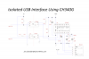
Problem is im not really sure where to start - i started to make a rough circuit (picture attached) however there wasn't a square wave on the output and i wasn't receiving the right data the other end.

Thanks for your time.

upload_2017-2-23_21-21-37.png
 
Which specific variant of the optocouplers do you have on hand? We need to check the Current Transfer Ratio.

You will need to get more current into the diode. Knowing the CTR, we can suggest a pull-up resistor on the output side.
 
Does a dsPIC provide the same 25mA drive capacity of the 16Fs and 18Fs? If I recall correctly, maybe not and you'll need to buffer its transmit line.

Here a circuit I'm using between an 18F PIC and a CH340. Works perfectly at 9600 baud.
 

Attachments

  • Isolated_USB_Interface_Using_CH340G_-_1200px(2).png
    Isolated_USB_Interface_Using_CH340G_-_1200px(2).png
    86.2 KB · Views: 137
I use "Digital Isolators" The SI8421 is not for new applications. Will be phased out. Look at any Digital Isolator. You do not have to worry about LED current or CTR. You just send TTL into one side and get TTL out the other side. The 8421 is a dual part with one facing right and the other facing left. (in that family there is also a dual where both isolators are facing the same direction)

See ISO7221:
upload_2017-2-23_17-40-11.png
 
Hi MikeMI,

This is the device sorry, spec also attached.

Jonsea yes i'm ideally looking for low-power

Ronsimpson i will look into them also in future they look a lot easier to get going.

Thanks
 

Attachments

  • octo.png
    octo.png
    33.5 KB · Views: 122
You did not mention the actual rise and fall time measurements, but at 9600 baud rise and fall times of less than 5 us should be fine.
 
The A-2 has a min CTR of 0.6, so if you can get 5mA into the LED, you will be able to sink about 3mA at the collector.

I am guessing that your PIC can source 5mA at a voltage drop of ~0.3V, so R1 (designator in your sim) will have 3.0V at one end, and 1.25V (the Vf of the input LED @ 5mA) at the other end, so R1= (3-1.25)/5m = 350Ω.

R2 will have 3.3V at one end, and Vce(sat) at the other when the collector current is 3mA, so R2 = (3.3 - 0.5)/3m = ~ 1KΩ.

Get rid of R3, it only makes it worse....

The speed of the opto is more than sufficient at 9600 baud at these current levels...

Since the configuration you showed originally in your sim inverts, I think you want to wire the input LED so that its anode is tied to 3.3V, and its cathode goes to the transmitting port pin. That doesn't change the math enough to worry about.
 
Last edited:
Status
Not open for further replies.

Latest threads

New Articles From Microcontroller Tips

Back
Top