Continue to Site

Welcome to our site!

Electro Tech is an online community (with over 170,000 members) who enjoy talking about and building electronic circuits, projects and gadgets. To participate you need to register. Registration is free. Click here to register now.

  • Welcome to our site! Electro Tech is an online community (with over 170,000 members) who enjoy talking about and building electronic circuits, projects and gadgets. To participate you need to register. Registration is free. Click here to register now.

HELP needed with TL783 Regulator Circuit

Status
Not open for further replies.
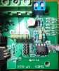
Looks like it shouldn't be too difficult to uprate that controller if we can find out a bit more about it. The FET is only rated at 100V so could be swapped out. Can't read the numbers on IC1 ?
Don't suppose you have a schematic for the controller?

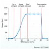
I wish I did !!... Whilst the engineer at SWEA, a guy named Mari has been very co-operative on most things. His solution to the problem is that I buy a seccond contoller and run them in serries. In theory this will work, but I am not convinced as I think there would be some hysteresis problems between the two controllers. The 100v rating for the FET is actualy OK on this device, because its ability to limit voltage is so good it compleately stops any rise dead 2v above its set point

He says he will look into my request for uprating the voltage, but he's always too busy to actualy do it !.

Here is a link to the data sheet for the 10F204 IC

https://ww1.microchip.com/downloads/en/DeviceDoc/41239D.pdf
 
Last edited:
Pins 4 and 5 of IC1 are presumably being used for analogue measurement/comparison, so it would help if the circuit around them, at least, could be traced out. A mod of a couple of resistor values, plus a FET upgrade (optional if 100V limit is not exceeded), may be all that's needed. Does the blue connector normally have a 5V or similar input from a wall-wart?
 
Pins 4 and 5 of IC1 are presumably being used for analogue measurement/comparison, so it would help if the circuit around them, at least, could be traced out. A mod of a couple of resistor values, plus a FET upgrade (optional if 100V limit is not exceeded), may be all that's needed. Does the blue connector normally have a 5V or similar input from a wall-wart?

The blue connector is normaly unused. Its an option to connect a small wall PSU in order to keep the inverters in an ON state. However its not actualy needed because the dump load circuit is self powering and I am happy with the inverters powering down when not in use.

I am hopefull that I will be able to obtain a circuit diagram for the SWEA controller by tomorow.
 
Last edited:
Does your turbine have a vane to turn it out of the wind if the wind is to high?
 
Does your turbine have a vane to turn it out of the wind if the wind is to high?

??What??.... It has a vane yes, but this helpt to keep it IN the wind !. If the wind gets to high the dump load reduces the speed of the turbine. If that is damaged or not working, then the blades deform under the centrifugal force of rotaing at high speed and this is the last line of defence against over speading.
 

Attachments

  • Wind-Turbine-Power-Curve.jpg
    Wind-Turbine-Power-Curve.jpg
    18 KB · Views: 174
Most have something like this:

https://www.thebackshed.com/Windmill/Docs/Furling.asp

So their output looks like this:

If yours it like this PWM would be easy since you are not using all of it's power.

Somthing like that, exept the turbine doesnt stop when there is too much wind, its speed is simply limited.

Presently the settings for my Mastervolt Wind master are as follows:

Switch on ) 28v - 0A
Set point 1) 56v - 1.5A
Set point 2) 70v - 3.0A
Set point 3) 76v - 4.0A
Set point 4) 85v - 6.4A

This gives a maximum grid output of 544W. However at full power the inverter will consume up to 600w, with 56w going to heat dissipation.

I just received the Circuit Diagram for the SWEA Dump Load controller and like I said this circuit works realy well. But unfortunately is limited to 58v max. If it could be modified to be adjustable between 85v -95v, then I think that would be perfect.
 

Attachments

  • APboxCktAPboxschema27-10-06.pdf
    6.4 KB · Views: 229
Last edited:
Good to have the schematic. Seems the schematic differs slightly from the circuit in the posted photo. What are the values (or the colour bands.....can't tell the colours from the photo) of the two standing-on-end resistors near the red LED?
I assume those resistors are a substitute for R4 and the 10k trimmer in the photo is R6.
Can you confirm that the on-end resistor nearer the IC goes to one end of R1 and that the on-end one further from the IC goes to the trimmer? Edit: or does it go to the yellow LED anode?
 
Last edited:
Good to have the schematic. Seems the schematic differs slightly from the circuit in the posted photo. What are the values (or the colour bands.....can't tell the colours from the photo) of the two standing-on-end resistors near the red LED?
I assume those resistors are a substitute for R4 and the 10k trimmer in the photo is R6.
Can you confirm that the on-end resistor nearer the IC goes to one end of R1 and that the on-end one further from the IC goes to the trimmer?

The diagram is supposed to be for the exact circuit shown in the photo !.... However I can also see some differences too ?

There are two serries connected resistors totaling 797K in the vertical position (R4) and I assume this was to get the right value. They are connected at one end to pin 5 of the IC and to the trimmer at the other end. The trimmer which is not shown on the drawing has a maximum value of 105K when measured with my meter. This device is placed between R4 and the positive rail.

R3 has been replaced with a 3.9K resistor and not 8.2K as shown in the drawing.
R7 has been replaced with a 120K resistor and not 180K as shown in the drawing.
 

Attachments

  • 003.JPG
    003.JPG
    143 KB · Views: 165
Last edited:
Yeah, nice cap.
The trimmer is placed between R4 and the positive rail.
By 'positive rail' do you mean the +6V2 supply to the IC or the +ve rail of the turbine/inverter? I would have expected it between R4 and ground.
Is there a 10k fixed resistor (R6) between R4 and ground in the actual controller you have?
 
Yeah, nice cap.
By 'positive rail' do you mean the +6V2 supply to the IC or the +ve rail of the turbine/inverter? I would have expected it between R4 and ground.
Is there a 10k fixed resistor (R6) between R4 and ground in the actual controller you have?

No.. I thought that at first, but then I checked. It would apear that what they have done is to reduce the value of R4 and then insert the trimmer to make up the difference.

R6 is the 10K resistor just to the left of the IC.

Please see the photo I put in my previous comment after editing it.
 
Last edited:
It would apear that what they have done is to reduce the value of R4 and then insert the trimmer to make up the difference.
I see.
R6 is the 10K resistor just to the left of the IC.
I did wonder.
I would like to use my existing SSR
What are its input drive requirements?
 
Some numbers:
Based on the voltage drop when the load switches in the internal resistance of the turbine would come out about .83 ohms. If you use that value an additional load of 8 ohms would keep the voltage above 85 volts so no power loss from the inverter. It would appear the 1 KW rating is right at 100 volts at 10 amps using those numbers. You could then add another switch that turns on at say 97 volts turning on the other 8 ohm resistor. Assuming their are two 8 ohm resistors available. This would keep the total load the same as it is now. The turn off points could be around 87 and 90 volts. A poor mans pwm.:D In any case the numbers may come in handy when trying to set the duty cycle on the board.
Power loss in the turbine at full power -- 83 watts

PS. Yes the FET on the board is only rated at 60 volts.
 
Last edited:
Some numbers:
Based on the voltage drop when the load switches in the internal resistance of the turbine would come out about .83 ohms. If you use that value an additional load of 8 ohms would keep the voltage above 85 volts so no power loss from the inverter. It would appear the 1 KW rating is right at 100 volts at 10 amps using those numbers. You could then add another switch that turns on at say 97 volts turning on the other 8 ohm resistor. Assuming their are two 8 ohm resistors available. This would keep the total load the same as it is now. The turn off points could be around 87 and 90 volts. A poor mans pwm.:D In any case the numbers may come in handy when trying to set the duty cycle on the board.
Power loss in the turbine at full power -- 83 watts

PS. Yes the FET on the board is only rated at 60 volts.

No the FET is rated at 100v, please read the data sheet I attached previousley.

The solution you have suggested is rather complex, but interestng all the same. I think the idea presented by Alec-t for modifying the SWEA pwm controller was a better. I know that system works very well as I used it previousley on a lower voltage turbine.
 
Last edited:
@ronv
PS. Yes the FET on the board is only rated at 60 volts.
? we must be using different datasheets
IRLS4030.gif

@GoGreen
any voltage between 5-32v and negligible current.
Can you define 'negligible'? The IC can put out only ~3mA at close to 5V, so a buffer stage might be needed? Or were you thinking to use the FET to drive the SSR?
 
Status
Not open for further replies.

Latest threads

New Articles From Microcontroller Tips

Back
Top