Continue to Site

Welcome to our site!

Electro Tech is an online community (with over 170,000 members) who enjoy talking about and building electronic circuits, projects and gadgets. To participate you need to register. Registration is free. Click here to register now.

  • Welcome to our site! Electro Tech is an online community (with over 170,000 members) who enjoy talking about and building electronic circuits, projects and gadgets. To participate you need to register. Registration is free. Click here to register now.

Help needed on designing a circuit for a digital clock (A level project)

Status
Not open for further replies.
Here is the circuit, it is accurate, i used the oscilloscope in croc tech and it measured it in its own simulation time.
 

Attachments

  • new-3..jpg
    new-3..jpg
    539.3 KB · Views: 337
Yes, the transistors are connected as emitter followers as I said above.

You could replace the hex inverter with six transistors, configured as common emitters, but you'll still be restricted by the output current of the wimpy CMOS CD4017 so it won't get you anywhere.


My advice is to rip out all the transistors and replace all CD4000 series ICs driving LEDs with 74HC equivalents and the LEDs will work at full brightness.

Don't worry if Crocodile Clips doesn't have models for the 74HC series, you've proven the logic.

I was wrong earlier when I said you only need six ICs, you'll need another IC or two to convert the 1Hz signal from the 4060 to 1/60Hz, I'll see if there's an easier way to do it.

I suggest you re-read the last couple of pages and do some more research on logic families and transistor configurations (common emitter, emitter follower).
 
But the problem with the hour LED's is that the nedative ends of the leds are going through the JK flip flop , and using its 0v-rail. The flip flop is the thing that is limiting the brightness.
 
Last edited:
Why would the flip-flop limit the brightness any more than the 4096?

Sorry but that's not true. I told you why the LEDs will be dim.

See for yourself my measuring the voltages around the circuit.

I told you what you can do about it.
 
well ive done the circuit now, i fixed the problem, just by adding two transistors, and all the LED's are at full brightness and the clock is in time.
Now i Just need to make the circuit for the 1 min time base...
 
Good glad you got it working.

What about adding a second hand or do you already have enough LEDs?:D

If you use a 32768Hz crystal then the output from the 4060 will be 2Hz. You could use a divide by 12 and a divide by 10 counter to divide by 120 to get 1 pulse per minute.
 
No that's enough LED's thank you :p
well yesterday i ordered a 3.2768 MHz crystal (30PPm) which should arrive shortly. What should i use for that?
I bought that one because of the diagram of the 1 min time base mbarazeen posted.
 
Last edited:
No that's enough LED's thank you :p
well yesterday i ordered a 3.2768 MHz crystal (30PPm) which should arrive shortly. What should i use for that?
I bought that one because of the diagram of the 1 min time base mbarazeen posted.

It's not the most efficient way but it'll work.

Yes please do post pictures when you get it working.
 
Yes, I've just said that.
 
for 12 hour, you still can use two 4017 as you used for 60 min LEDs. make a matrix of 6x2. so you dont want to use a flip flop or a AND gate.
 
Last edited:
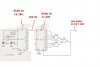
okay, for the minute circuit, how will the crystal start to resonate? because there is nothing to set it resonating, well, im not sure if there is. And for the whole circuit, everything that needs electricity, ie, chips, LED's, are connected to a common voltage rail, and so are all the negatives. I bought a 5v DC supply, 2 amps. Im really worried that this will be too much, and blow components.
Everything that takes power is in parallel, there are no resistors before the power pin on the chips, but there are 220 ohm rsistors before the LED's.
Any thoughts?
 
Oh no not another one. ;)

The 2A, 5V power supply is more than good enough to power the circuit without a problem.

Why on earth would you put resistors in series with a digital IC's power supply pins? That's probably about the worst thing you can do.

Don't worry, the crystal will soon resonate, when the supply voltage is applied it'll give it a kick.
 
Last edited:
I haven't, i was just worried that it might blow some components?

But for the minute pulse circuit, ive designed it how it is on the photo, and the only thing the supply voltage is powering is the two divider chips, and the triple 3 input and gate. The two capacitors are only connected to ground.
 

Attachments

  • time base-2..JPG
    time base-2..JPG
    36.9 KB · Views: 259
and here's the actual clock, it onlt has 3 peices of acrylic fixed into it at the moment, and 10 LED's, because im working on the circuit.
 

Attachments

  • DSC00793..JPG
    DSC00793..JPG
    763.6 KB · Views: 291
I haven't, i was just worried that it might blow some components?
As I've said before, the power supply is more than adequate for what you're doing.

The maximum current rating is well in excess of what your circuit needs which is good.

It's a switched mode power supply which means the 5V will be nicely regulated and free from potentially damaging voltage spikes.

Providing you connect everything up correctly, you won't blow any components, that'll only happen if you make a mistake.

But for the minute pulse circuit, ive designed it how it is on the photo, and the only thing the supply voltage is powering is the two divider chips, and the triple 3 input and gate. The two capacitors are only connected to ground.

Well, all the 0V pins on all the ICs need to be connected to ground too.

For stability's sake you should connect a 100nF capacitor across the power supply pins of each IC.
 
Status
Not open for further replies.

New Articles From Microcontroller Tips

Back
Top