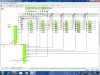
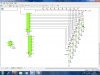
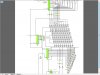
I did that circuit in croc tech, but the LED's arent receiving enough power?
Is there any way to add external power to the LED's?
I realised that might be a problem after I posted it.
It's because the CMOS outputs have quite a high resistance.
Increasing the supply voltage will help.
Under a certain supply voltage you can omit the series resistors with CMOS so you might want to try that.
Another option is to move to move to HC because it has a higher output current, that is assuming you can get the 4017 in HC flavour.
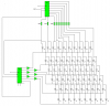
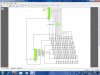
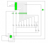
Here's a an efficient way of doing the hour counter. You can use the other JK flip-flop on the CD4027 in the same way to convert the 2Hz from the CD4060 to 1Hz to drive the whole counter with.
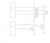
Rather than using another IC for the AND gate you might be able use a couple of diodes and a resistor, I'll post a schematic if you're not sure.
I have a concern about the resetting of both of these circuits, it might work in the simulation but there might be problems in real life. The trouble is different ICs are being used and they will be on different parts of the PCB. This means that one IC might reset before another and its output could change before the other IC is set. This race condition could be solved using some RC circuits to ensure that the most important one resets first. Anyway I suggest breadboarding it before you make a proper PCB or solder it on a strip-board.
I have an old version of Crocodile Clips and although it's easy to use, it's not a very powerful simulator. I haven't tried the latest version but I wouldn't expect it to be that much better. I've moved on to more powerful software since leaving school but I still use Crocodile Clips for schematics or simulating very simple circuits or logic gates.

 .
.