Continue to Site

Welcome to our site!

Electro Tech is an online community (with over 170,000 members) who enjoy talking about and building electronic circuits, projects and gadgets. To participate you need to register. Registration is free. Click here to register now.

  • Welcome to our site! Electro Tech is an online community (with over 170,000 members) who enjoy talking about and building electronic circuits, projects and gadgets. To participate you need to register. Registration is free. Click here to register now.

Help for circuit.

Status
Not open for further replies.

arm755

New Member
Hi.

I need help with a circuit for 12 volt use. If some relays can be used, great.

When +12v switch is turned on: 1 (-) pulse output 3 seconds.
When the same +12v switch is turned off: another (-) pulse output 3 seconds.

Has somebody an Idea of how to do this?

Best Regards.
 
What do you mean by (-) pulse?

What do the pulses do?

How is the +12V switch wired? One end to +12V? Other end to what?

A diagram would help: show +12V, ground, the "switch", and the loads to be controlled with the pulses...
 
This is for a aftermarket car alarm use. The siren output of the alarm main controler is a +12 v output. When this siren output is ON or + 12 volts, I need a device that, once conected to that siren output, will give a -12v pulse output for 3 Second once ON, and when the siren output is turned OFF, once again another -12v pulse output for 3 seconds. This pulse outputs will be used to activate/deactivate the turne signal lights that o this car is controled completly by canbus type comunication and can not be hardwired.
 
I am still confused by the term "-12V pulse output".

Do you mean that you need an output that normally sits at +12V (actually more like 14.4V if the car is running) that you have to pull to ground for 3 seconds? Is that what you want to use a relay contact for? How much current would the relay be sinking? In other words, what is connected between +12V and the relay?

Is this what you mean:

rly.png
 
This pulse outputs will be used to activate/deactivate the turne signal lights that o this car is controled completly by canbus type comunication and can not be hardwired.
How do you propose to use the relay contacts to activate the turn signals?
 
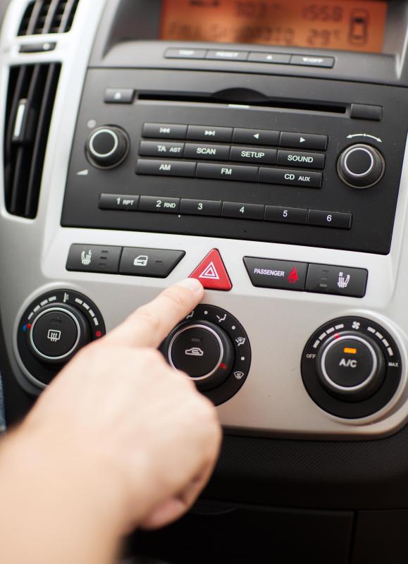
hand-pushing-hazard-light-button.jpg


The relay will be used to close a circuit between 2 cables, witch circuit is normally closed by pressing the emergency light button (parking light button), and that way turn on the turn signal lights when the siren is ON. Simple.

The emergency light button (parking light button) is a simple push switch that close a circuit between 2 cables to turn on the turn signal lights and again you must press that push switch to close again the same circuit between those 2 cables to turn them off.
 
Last edited:
I would suggest using an exclusive or gate. One input connected directly to the switch output and the other input via a resistor (Say 10K) and a capacitor (Say 100 nF) between that input and ground. The output will pulse high for the short time that the inputs are different. The output of this could then trigger a NE555 timer to produce the 2 to 4 second delay. It MIGHT even work without the 555 just by having a longer time constant for the capacitor/resistor delay network on the input of the exclusive or gate. As you would probably use a cmos gate you would need a transistor on the output to provide enough current to drive a relay.

Les.
 
Ok. I don't see why you need a 2-3S 'on' time for the relay. Surely the CANBUS will respond in a fraction of a second? If so, a non-polarised relay could be be very simply double-pulsed using a SPDT switch and a fat capacitor, like this :-
RelayToggle2.JPG
C2 is the fat cap. C1 is for voltage spike suppression.
 
You need the 2-3s 'on' time for the relay to imitate your finger when You push the button. One push to the button to activate the turn signal lights, second push to the button to desactivate the turn signal light.
 
I would suggest using an exclusive or gate. One input connected directly to the switch output and the other input via a resistor (Say 10K) and a capacitor (Say 100 nF) between that input and ground. The output will pulse high for the short time that the inputs are different. The output of this could then trigger a NE555 timer to produce the 2 to 4 second delay. It MIGHT even work without the 555 just by having a longer time constant for the capacitor/resistor delay network on the input of the exclusive or gate. As you would probably use a cmos gate you would need a transistor on the output to provide enough current to drive a relay.

Les.
Can You make a diagrama for that. Thanks in advance.
 
This circuit should do what you want. I had forgotten that thew 555 requires a negative trigger pulse so I have used one of the XOR gates in the package as an inverter. ( You could use an 4077 instead of a 4070 and you would nit need to invert it's output.)
Pulser01.png


The large decoupling capacitor (C6 1000 uF ) are to try to make it less likely to be triggered by noise on the 12 volt supply.

Les.
 
This circuit should do what you want. I had forgotten that thew 555 requires a negative trigger pulse so I have used one of the XOR gates in the package as an inverter. ( You could use an 4077 instead of a 4070 and you would nit need to invert it's output.)
View attachment 101185

The large decoupling capacitor (C6 1000 uF ) are to try to make it less likely to be triggered by noise on the 12 volt supply.

Les.
Interesting. I will try it out and see if it works. Thank You very much. Is the 555 necesarry or could it work with a transitor?
 
Could someone enlighten me on why do the hazard lights need to be held for three seconds before they start working? I don´t know how it goes in the US, but here in Europe if you go on a highway and have to brake suddenly so you don´t hit the end of a congestion (caused by an accident or whatever) you immediatly turn on the hazard lights so that you don´t get rear-ended. Three seconds delay is the difference between life and death if there is less than perfect visibility.
 
Could someone enlighten me on why do the hazard lights need to be held for three seconds before they start working? I don´t know how it goes in the US, but here in Europe if you go on a highway and have to brake suddenly so you don´t hit the end of a congestion (caused by an accident or whatever) you immediatly turn on the hazard lights so that you don´t get rear-ended. Three seconds delay is the difference between life and death if there is less than perfect visibility.

Can be 1-2 seconds depending on your finger pressing speed. Thanks for your help on the main issue.
 
View attachment 101183

I hope this diagram will leave it more clearly on how the emergency light button Works:
arm755:

This clears it up...

However, I would like you to make a couple of measurements with a DVM.

1. Set the DVM to DC Volts mode to read ~15V. Put the red probe on the "BSI/ECU" signal. Put the black probe on car's ground (chassis ok). Measure the open-circuit voltage and tell us...

2. Set the DVM to DC mA mode, start on the 1A scale. Put the red probe on the "BSI/ECU" signal. Put the black probe on car's ground (chassis ok). Measure the current. You may have to make the meter more sensitive. Do not be surprised if you turn on the flashers while making this test. Tell us the current reading with probes connected.
 
Pending the outcome of the measurements I asked you to make in post #17, here is circuit that probably does what you asked for. Without having your current measurement, the one caveat is can the LM393 sink enough current to pull V(bsi) low? If after you make your measurement the answer is no, then there is a simple mod that will boost the current sinking ability of the circuit.

I am using a window comparitor circuit to drive the bsi output pin. The alarm signal is differentiated, and the two comparitors detect if either the alarm signal just turned on, or just turned off.

There is a start-up inhibit part to this circuit, to prevent a spurious output during application of power.

The two LM393 comparitors are available as in a 8pin dip package. The Accy line is just a fused version of the car's power. The dashed box on the right is my guess of what is inside the ECU. You will confirm my assumption if you make the measurements I asked for.

16.png
 
One push to the button to activate the turn signal lights, second push to the button to desactivate the turn signal light.
:banghead: That isn't what you asked for originally. The original post wanted switch closure and switch opening each to generate a pulse. Our efforts so far have been aimed at that original requirement.
 
arm755:

This clears it up...

However, I would like you to make a couple of measurements with a DVM.

1. Set the DVM to DC Volts mode to read ~15V. Put the red probe on the "BSI/ECU" signal. Put the black probe on car's ground (chassis ok). Measure the open-circuit voltage and tell us...

2. Set the DVM to DC mA mode, start on the 1A scale. Put the red probe on the "BSI/ECU" signal. Put the black probe on car's ground (chassis ok). Measure the current. You may have to make the meter more sensitive. Do not be surprised if you turn on the flashers while making this test. Tell us the current reading with probes connected.

Mike Mi.

This would be not necessary since I will use the same 2 original cables the hazard light push switch uses, and make the micro relay do the job of the push switch. Simple.

The grounded cable on the diagram is the original cable that I measured and actually is grounded.

The other original cable as You can see on the diagram goes to the BSI.

The current use must be small since both 2 original cables are thin cables.
 
Last edited:
Status
Not open for further replies.

Latest threads

New Articles From Microcontroller Tips

Back
Top