Continue to Site

Welcome to our site!

Electro Tech is an online community (with over 170,000 members) who enjoy talking about and building electronic circuits, projects and gadgets. To participate you need to register. Registration is free. Click here to register now.

  • Welcome to our site! Electro Tech is an online community (with over 170,000 members) who enjoy talking about and building electronic circuits, projects and gadgets. To participate you need to register. Registration is free. Click here to register now.

Help Deriving a Circuit

Status
Not open for further replies.
Thanks for the update Quietman. I will take some time to review your changes and understand the purpose and significance of these changes. I have never done any PCB designing, but will look into that software and any files you also provide.

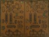
As to your point about the PIC project (and to any body else curious)- I have in the meantime been going on a parallel path and learning some C and attempting to come up with a design of my own (to all, please be aware of my lack of experience if my design is horrid, but I've seeked assistance in the electrotech chat frequently). Below is the latest circuit schematic from this off-shoot project:

http://i.imgur.com/U4Lsr.png (NOTE HIGH RES! Why I didnt include it in the actual post. Also some of the notes about the resistor watt rating may no longer apply)

I initially started trying to have individual control of all the LEDs, but with 700mA per LED I didnt think it was feasible. Instead I have it arranged as 2 LEDs in series, 1 LED, then another 2 in series per bank. This at least would give me a little bit more flexibility for flashing patterns. As for the POT connected to pin7... I used the ADC value to set the delay in some flashing patterns (as chosen by the rotary switch). Thus by changing the delay i could theoretically increase/decrease the flashing rate. Not sure if that's the best way to go about it but thats how I approached it. I also thought LM338 were a good choice because of their high current (5A) support... I also considered this: http://www.reuk.co.uk/LM317-High-Current-Voltage-Regulator.htm as a way for a high current voltage regulator... Anyway, I'll appreciate any points about this circuit, and I look forward to seeing how your circuit progresses.

Best!
 
Last edited:
you seem to have your OUT & ADJ pins backwards

There's only 1.25 volts across that resistor, so @ 72mA, that's 0.091W - you could just use a single 18 ohm 1/4W or 1/8W if you wanted. The heat will mainly be dissipated by the LM317.

OK, I drew the schematic wrong, it is corrected. Thanks for the catch, both of them.

police-lights-12-gif.57765


I am having an off day, it is supposed to be 12Ω, and 7X of them will be 729ma. I knew this, but wrote down the other anyhow.

Now to start the Express translation.
 

Attachments

  • Police Lights 12.GIF
    Police Lights 12.GIF
    9 KB · Views: 403
Last edited:
OK, you can download ExpressPCB here...


It if free and legal.

I am attaching my Express schematic, which is the first step in making a PCB.
 

Attachments

  • Police Lights 12.sch
    25.1 KB · Views: 128
OK, finished the basic layout. Time for trace cleanup (it is an extra step, I like certain conventions on my pads). At this point I'll take the .pdf files, and use Gimp to convert them to .gif files. Then I will use M/S Paint to modify the images a bit.

The finished board will be 4" X 2.65"
 

Attachments

  • Police Flasher 12 Silkscreen.pdf
    10.2 KB · Views: 305
  • Police Flasher Copper side.pdf
    18.1 KB · Views: 223
  • Police Lights 12.sch
    27.3 KB · Views: 119
  • Police Lights.zip
    79.5 KB · Views: 120
Last edited:
To match the final Vf of the two legs to something close, so as to minimize any transition pulse when switching between them. The two Red LEDs will drop around 5V, while the two Blue LEDs will drop around 7.2V. It is to not spike some very expensive LEDs with a transient. Probably not needed, but better safe than sorry. I bought a reel of several thousand 1N4007's for $1 a while back.
 
Last edited:
You asked, I explained. You don't have to agree with me, and I don't have to agree with you. I'm doing the designing, so I get to make the decisions. Life is good.
 
Please tell me how a diode is going to suppress a spike.

WARNING: DO NOT DELETE A MODERATORS MESSAGE..... ABUSIVE COMMENTS
 
Last edited by a moderator:
Your circuit is far too complex.
You only need a current limiter driver transistor for each output as shown in the third diagram. You will need a power transistor for currents above 100mA:
**broken link removed**
 

Attachments

  • Fig71a.gif
    Fig71a.gif
    5.4 KB · Views: 208
Last edited:
Nice try, but again, I disagree. My suggestion is to find someone else to pester, cause you have no traction with me. You can deliberately misunderstand all you want, I don't care. If you ask a civilized question I will explain as I have in the past.

But just in case you really are not getting it, the idea is remove a major voltage transit. Since all electronics takes a finite time to adjust, the smaller the voltage transit the quicker the current regulator will compensate for the voltage shift. It really is simple, you should be able to understand the concepts explained. I believe I mentioned it was a better safe than sorry add on, and dirt cheap.

For the audience Collin55 has bumped heads with me in the past. We are not friends, and he is being disingenuous with his posts. If necessary I will add this disclaimer onto every thread he pesters me. I can document past conflicts if requested.

However, back on topic.

Here is the print I have cleaned up. I used my own standards for the pads. Now to etch some boards.

I used Gimp to translate the .pdf files into large 600dpi .gif files, and will use Gimp to print them out on my laser printer.
 

Attachments

  • PL12 prints.GIF
    217.8 KB · Views: 163
Last edited:
If you want current limiting for the LEDs, in case of a spike, the current limiting resistor in my current-limiting driver circuit will provide the feature. You have no resistor in your design.
 
Last edited:
I've finished making the transfers, now to put them on copper.

If anyone is curious how I do this, I posted a tutorial on AAC.

How I make PCBs

Give it up Collen. My design is finished. I think it is obvious what you are doing, and it isn't trying to help.
 
Last edited:
Now the hole guide...

hole-sizes-gif.58379


A trick I use for PCBs is to take pictures and use the images on the computer to inspect them. You can click on the attachments to see the finished boards, they will be larger than life. So far I haven't seen anything major. I have not cleaned them with scotchbrite, only Acetone.
 

Attachments

  • Hole sizes.GIF
    Hole sizes.GIF
    18 KB · Views: 339
  • PCBI01.JPG
    PCBI01.JPG
    107.4 KB · Views: 176
  • PCBI02.JPG
    PCBI02.JPG
    106.2 KB · Views: 172
Last edited:
On advise from 3VO I'm going to use a light coating of acrylic clear paint after scrubbing the board as a conformal coating. I'll try a throwaway first, to see if it works. He says the Acrylic will get out of the way of the solder.

I'm going to make some test power LEDs using 1N4007's in series to drop the same about of voltage, or close to it. I'll put some weak diodes in series (with a resistor of course) to show them lighting. It will allow me to test the circuit. If I get some high power LEDs I show it properly, either way it will be on You Tube.

While not a pretty pictures, here is the silk screen.
 

Attachments

  • 100_4388.JPG
    100_4388.JPG
    62.8 KB · Views: 177
Status
Not open for further replies.

Latest threads

New Articles From Microcontroller Tips

Back
Top