Continue to Site

Welcome to our site!

Electro Tech is an online community (with over 170,000 members) who enjoy talking about and building electronic circuits, projects and gadgets. To participate you need to register. Registration is free. Click here to register now.

  • Welcome to our site! Electro Tech is an online community (with over 170,000 members) who enjoy talking about and building electronic circuits, projects and gadgets. To participate you need to register. Registration is free. Click here to register now.

Help Deriving a Circuit

Status
Not open for further replies.
look at post #7, but that curcuit needs a little mod. There is another post describing what could be done.
 
.........
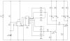
If all you want is an alternate flasher, which I am coming to believe is what you want, then simple conventional MOSFETs would work well. They are cheap, reliable, and need very few extra parts.

So I am asking flat out, are you only wanting to alternate between two banks of LEDs (I assume at ½ second intervals)? If so I can sketch up a simple schematic....

....Rereading the post I have to ask if you want the circuit shown on post #24?

-Yes, the goal is an alternating flasher, that would flash two times or three times per bank and then alternate. Ideally, the speed would be variable/adjustable.

So a suitable flashing pattern (L bank vs R Bank) would be: LLL RRR LLL RRR etc (or LL RR LL RR LL). I like the effect of three flashes better than two, but as you said I'd like to keep it stupid simple. I do not want just a single flash that then alternate.

-As for the circuit from post #24, that was something I found and just recreated for better resolution. Unfortunately, it flashes LLL RR LLL RR. I still havn't figured out what was wrong with it, but again its not my circuit like I earlier said, just something I found and wanted to add to the thread as information :D !
 
Yes, it looks as if it should work correctly (although there's at least one error on the schematic: there's no "10" pin on that chip). In fact, my money'd be on that circuit at this point, with the addition of MOSFET switches for the LEDs. Nice low parts count.
 
okay^ maybe my simulation is incorrect.
Your simulation is likely correct. Try changing the counter outputs to reflect the attached image.
 

Attachments

  • fu0zD-1.jpg
    fu0zD-1.jpg
    59.7 KB · Views: 175
Hmm, it looks as if all that's going to do is to even out the first 3 pulses. How would that fix only 2 pulses on the other side (outputs 5, 7, & 9)?

I think the simulation was wrong.
 
Your simulation is likely correct. Try changing the counter outputs to reflect the attached image.

Yes you are correct. I made a mistake in re-doing the circuit. Changing that wire as you indicated results in the three flashes! LLL RRR LLL . Thank you for finding that mistake. It simulates correctly now.
 
Here is the fixed schematic: wire fixed, and i changed one resistor to a a variable resistor that changes the speed if flashes:

**broken link removed**

I like the simulation.
 
Below is a schematic based on the suggestions from before and some help from the user Meming in chat.
**broken link removed**

I cleaned up the circuit a little (also reversed which LEDs initially turn on first), added two banks of four LEDs, deleted the resistors that followed the diode outputs, changed the battery output to 12V (car cigarette lighter), and replaced the transistors with mosfets.

LEDS1-4: are to be white
LEDS5-8: are to be red

I'm thinking about these LEDs for sale on ebay: **broken link removed**
Specifications are at the bottom of the page. In case the ebay link is outdated here is a picture of the specs: Link

Based on the specs is it correct that R2 and R3 (for the White LEDs) need to be 6 Ohms, and for R4 and R5 (for the Red LEDs) to be 10 Ohms?

For the MOSFET is the IRF510 ( Link ) appropriate?
Any specs for the diode?
 
Last edited:
looks like you've got the hang of it. I didn't check your links. Just a note regarding R6/R7 - they're a little small. The 4017 doesn't have much drive capacity, so you may want to increase R6/7 to 10k.
 
Not a bad schematic. It is not what I would use, but it works, and it is pretty close to one way I would do it.

One of the reasons I like MOSFETs is (if properly designed) they don't get hot like BJTs. My average MOSFET in my bin box starts at 25A, and goes up from there, so those LEDs are not going to be a problem. They also interface with CMOS quite well, they take just a breath of current to make them switch.

Here is a schematic I built for an RC car, it is useless for this application however. The flash pattern matches what you are after is the only reason I mention it.

temp2-gif.57405


I did a YouTube shot of it working...

https://www.youtube.com/watch?v=PcpLg9CCv3w

I'll make a similar drawing for something I would use. BTW, note the layout of lights on the car. It may be something you want to emulate.
 

Attachments

  • temp2.GIF
    temp2.GIF
    56 KB · Views: 334
Last edited:
First draft...

police-lights-5-gif.57403


The resistors R5-7 and R9-11 will have to be recalculated depending on the exact LEDs you buy. I just noticed I messed up a little, but since this is the first draft I'll let it stand.

Part of the reasons for the changes is I wanted a cleaner switching signal for the MOSFETs. That and it is simpler IMO.

The resistors will get warm, however they are only on 1 out of 10 cycles, so they aren't going to get that hot. I decided in terms of redundancy for the design. It would get less warm if two of the LEDs were in series, but if a LED fails with my way the other two will keep on working.
 

Attachments

  • Police Lights 5.GIF
    Police Lights 5.GIF
    7.5 KB · Views: 326
Last edited:
but..but... that's [almost] the same thing... just the diode ORs have been replaced with CMOS AND gates (making it completely non-functional, oops)
 
Non-Functional? Yeah, your right, it need OR gate. BRB, drawing. It does provide cleaner drive for the MOSFETs, which I mentioned, as well as reducing parts count. Yes, it is close to the original design, I not too proud to use other peoples ideas, especially when it is what the OP wants.
 
Last edited:
OK, Version 1.1

police-lights-5-gif.57406


Good catch, thanks.
 

Attachments

  • Police Lights 5.GIF
    Police Lights 5.GIF
    7.6 KB · Views: 435
Nice work on version 1.1! I was going to tweak the previous schematic I drew to reflect your design but unfortunately the program I'm using doesn't have 4 input OR gates. Not a big problem though, I'll figure something out. Let me ask, if I wanted to add another LED per bank would you recommend adding another in series or tacking one on in parallel. I think if I added it in parallel it wouldn't be a problem for the voltage requirement or for the MOSFET, but if I add one in series I think there may be a problem with voltage and I don't know about the MOSFET.

Also, did you/anyone take a look at the LED links I posted in post #53? Just wondering if you think these are okay. They are cheap and come from Hong Kong I believe.
 
Status
Not open for further replies.

Latest threads

New Articles From Microcontroller Tips

Back
Top