Continue to Site

Welcome to our site!

Electro Tech is an online community (with over 170,000 members) who enjoy talking about and building electronic circuits, projects and gadgets. To participate you need to register. Registration is free. Click here to register now.

  • Welcome to our site! Electro Tech is an online community (with over 170,000 members) who enjoy talking about and building electronic circuits, projects and gadgets. To participate you need to register. Registration is free. Click here to register now.

Help - capacitors hooked up right in LED array chaser?

Status
Not open for further replies.

R2-D2

Member
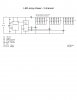
I have completed building the circuit I came up with - LED array chaser (schematic included.) Really cool effects to use with signs or advertising.

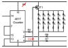
It does work but I am concerned about the caps I have across each LED array (C2, C3 and C4 shown in red.) They provide the fading on/off effect for each blinking LED array.

The question I have is - Do I need to protect the 555 and 1047 from those discharging caps even though they are connected across the LEDs? (I'm thinking as the caps discharge through the LEDs, they also discharge back through those ICs.) Maybe I need to include some diodes.

Any suggestions are appreciated.
Thanks!
 

Attachments

  • LED array chaser - 3 channel.jpg
    LED array chaser - 3 channel.jpg
    200.2 KB · Views: 681
The pot might burn out.
Why not use the transistors as emitter-followers and put the capacitor at the base of the transistors? Then the capacitor slowly charges and discharges through the base resistor.
Maybe a resistor must be added from the base of each transistor to the positive supply so that the capacitor does not dischage too far which would cause the LEDs to be turned off for most of the time.
 

Attachments

  • fading chaser.PNG
    fading chaser.PNG
    28.1 KB · Views: 713
Also there is no power on reset for the 4017.....attatched schematic ...........also add a capacitor from pin 5 to pin 1 of the 555- 0.1mf(pin 5 is the control voltage pin)......
 

Attachments

  • POR4017.pdf
    3.4 KB · Views: 322
Last edited:
A would add a 10 or 22uF electrolytic capacitor between pins 8 and 1 of the 555. Some times with out decoupling the 555 becomes erratic.
 
It was working erratic...

Thanks for your suggestions! I'll proceed with them and find out what happens.

Yes, without the cap you mentioned, the 555 was operating erratic when I hooked it up to a 12v battery source (8 x 1.5 AA battery pack.) For some strange reason, the 555 operated smoothly with a 9V battery (also without that cap.)

I figure this because the three LED arrays were periodically skipping or reseting in their chasing sequence out of the 4017 - strange but cool if you like things working in random:)

I'll see what happens when I connect the decoupling cap to it.
 
Last edited:
Status
Not open for further replies.

Latest threads

New Articles From Microcontroller Tips

Back
Top