Continue to Site

Welcome to our site!

Electro Tech is an online community (with over 170,000 members) who enjoy talking about and building electronic circuits, projects and gadgets. To participate you need to register. Registration is free. Click here to register now.

  • Welcome to our site! Electro Tech is an online community (with over 170,000 members) who enjoy talking about and building electronic circuits, projects and gadgets. To participate you need to register. Registration is free. Click here to register now.

[Help] 555 IC Keeps Blowing Up

Status
Not open for further replies.
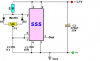
1) Don't use a MOSFET as a emitter follower (source follower) like in the schematic.
2) Transistors can have very low C-E voltage drop. It is common for the C-E voltage to be less than 0.6V. Maybe you are thinking about B-E voltage.
3) MOSFETs have high resistance Gate to Drain or Gate to Source. Maybe you are thinking about the resistance of D-S.

Sorry I ment to say Drain to Source.
And Yes the Load Must be: Supply to Drain.
 
A DRL is a Daytime Running Light that is supposed to be dimmed low beam headlights or maybe dimmed turn signals lights. Some stupid car companies (Fiat Chrysler, Kia and VW) use high beams at full brightness to blind everybody.
Why are you using a 555 oscillator at a low frequency to flicker the lights?
 
Adding resister (100 ohm) at output solved the issue.
555-v-13005.png
~chk~chk: /!\ PS /!\ -- all values blow are !! approximate/speculative
  • 12V sys , hfe.13005A=√(15·32)=22 , finding !! I.B values
    • (12.8-1-3·3.2)·1V/(40Ω/5)=280mA , /22=13mA , /9.4=30mA
    • (14.7-1-3·3.2)·1V/(40Ω/5)=510mA , /22=23mA , /9.4=54mA

  • 24V sys
    • (25.6-1-3·3.2)·1V/(40Ω/5)=1.8A , /22=80mA , /9.4=190mA
    • (29.4-1-3·3.2)·1V/(40Ω/5)=2.1A , /22=96mA , /9.4=220mA ***
. . . there might be higher I.B actual values as (using a speculative hfe normalization hfe.norm=2·√(22)=9.4 ***)
. . . above hoax is also not strictly following
555-v-13005-hfe~dr.png
__________
fast lab for MJE13005 with 4 in² heat sink mounted : R.CE.ON.min < 1Ω , hfe - depends on many along having a positive temperature coefficient (as junction getting hot passes ever more current)
555-v-13005-xp.png
 

Attachments

  • 555-v-13005-ds~unint.png
    555-v-13005-ds~unint.png
    13.9 KB · Views: 252
Last edited:
Better Yet, Use a Power Mosfet.

Transistors have a 0.6 Volt Drop, Collector to Emitter.
Corrected: Mosfets have a Low Resistance between the Drain to Source.

I soldered the things and fitted, works well so far. Yes, MOSFET should have been my first choice(at least for automotive stuffs), will do that next time.
 
A DRL is a Daytime Running Light that is supposed to be dimmed low beam headlights or maybe dimmed turn signals lights. Some stupid car companies (Fiat Chrysler, Kia and VW) use high beams at full brightness to blind everybody.
Why are you using a 555 oscillator at a low frequency to flicker the lights?

Yes, having on off ratio of 3:1 and cycle of around 10 times per second, you could barely see flicker from sideways but can notice little upfront.
 
The output of the 555 is about 1v lower than the supply and the base emitter voltage is 0.7v, so you are losing 1.7v with an emitter-follower configuration.
 
The output of the 555 is about 1v lower than the supply and the base emitter voltage is 0.7v, so you are losing 1.7v with an emitter-follower configuration.

I had to stick with emitter follower since wire from emitter alone is enough to power up led as I can use any near by metal parts as a ground whereas in collector follower I need to have a wire from battery positive to leds and its negative to collector. I don't want to see the wires going all across under the hood.
 
You used an NPN transistor as an emitter-follower when you should have used a PNP transistor or a P-channel Mosfet as a switch to feed the positive supply through resistors to the grounded LEDs.
 
You used an NPN transistor as an emitter-follower when you should have used a PNP transistor or a P-channel Mosfet as a switch to feed the positive supply through resistors to the grounded LEDs.

I want to have 3:1 on-off ratio, using pnp rather than npn will change my on-off ration to 1:3, and I read somewhere that you cannot achieve duty cycle lower than 50% that is more off time than on. So I doubt that I'll get same output by using pnp.
 
I want to have 3:1 on-off ratio, using pnp rather than npn will change my on-off ration to 1:3, and I read somewhere that you cannot achieve duty cycle lower than 50% that is more off time than on. So I doubt that I'll get same output by using pnp.

Actually you can, using a circuit that has 2 Diodes in it.
 
Actually you can, using a circuit that has 2 Diodes in it.

Yes, it will work as inverter I presume. Actually I want to do that in my circuit, since my drl is just below indicator lamp, incoming vehicles could not able see the turn signal clearly. So I should make drl go off when indicator is on, hope using inverter will solve this(don't wanna use relay). I can see variety of inverter solution(i.e RTL, TTL, CMOS) any suggestion that will work best for me.
 
Yes, it will work as inverter I presume.
No. The 555 still behaves as an oscillator, but the On and Off times can be independently adjusted to give a PWM output with a duty cycle variable from typically 5% to 95%.
 
Here's the circuit configuration that Alec is referring to:
Pot P1 allows adjustment of the output duty-cycle over a wide range.

upload_2017-5-22_13-8-30.png
 

Attachments

  • upload_2017-5-22_13-6-51.png
    upload_2017-5-22_13-6-51.png
    9.2 KB · Views: 225
found 13005 model ,
.model MJE13005 NPN(IS=2.58674e-10 BF=34.4393 NF=0.85 VAF=23.8713 IKF=4.47595 ISE=3.99999e-12 NE=3.5 BR=2.23806 NR=0.75 VAR=2.31727 IKR=9.69329 ISC=5.5e-13 NC=3.9375 RB=2.24801 IRB=0.1 RBM=0.1 RE=0.000429335 RC=0.105551 XTB=0.150853 XTI=1 EG=1.05 CJE=1.38055e-09 VJE=0.4 MJE=0.354762 TF=1e-08 XTF=0.05 VTF=0.1 ITF=142.836 CJC=1.68882e-10 VJC=0.4 MJC=0.347144 XCJC=0.1 FC=0.8 CJS=0 VJS=0.75 MJS=0.5 TR=1.91316e-06 PTF=0 KF=0 AF=1 Vceo=400 Icrating=8 mfg=On_Semiconductor)
, did some tests 555-v-13005-Rxp.png 555-v-13005-Rxp-b.png i can't see anything critical unless
  • the resistors are way lower than 40Ω
  • the led-s have a dropout below 3V
  • the switching speed or too slow transitions causes timer chip to overheat
  • or using the 13005 without appropriate heat sink ? significantly increases it's base current ?
  • in common emitter configuration the 13005 requires near-greater-equal but not less than 150Ω shunt from B to E
    -- see update @ #31
    -- i haven't used this particular bjt model in common collector - so i can't make guesses about
 
Last edited:
found 13005 model , did some tests View attachment 106106 View attachment 106107 i can't see anything critical unless
  • the resistors are way lower than 40Ω
  • the led-s have a dropout below 3V
  • the switching speed or too slow transitions causes timer chip to overheat
  • or using the 13005 without appropriate heat sink ? significantly increases it's base current ?
  • in common emitter configuration the 13005 requires near-greater-equal but not less than 150Ω shunt from B to E
    -- see update @ #31
    -- i haven't used this particular bjt model in common collector - so i can't make guesses about

Thanks for these statistics, may be I should do this for all my projects beforehand.

Being a web developer, I thought I'd never have to use math, I was wrong.
 
you can't trust the spice but 10% !!!
coz the models are simplified mathematical (theory -- what we "know"/guess/hope will happen)
and they are not quantum-mech. - thermodynamic (practise -- much more processor exhausting -- what there most likely will happen)

may be I should
the general rule is if something has worked so far -- don't change/loose it
while you may test the different approach don't switch to it until it has proven justified
 
i attempted to set up the 13005 based dimmer when i realized that the common collector e.g. an emitter follower setup is not good for current limiting/regulation
  • you can always make sure your led-s not over loaded by choosing the proper resistors **for max Vcc
  • but it's likely more reasonable to build your thing up from 2 modules
    1. a dimmer (generating proper waveform for ↓2.↓)
    2. a led switch (controlling the LED-s current) -- would also ensure enough brightness running from battery only**
as your next concern may turn out the LED-s not holding up
 
Status
Not open for further replies.

Latest threads

Back
Top