Continue to Site

Welcome to our site!

Electro Tech is an online community (with over 170,000 members) who enjoy talking about and building electronic circuits, projects and gadgets. To participate you need to register. Registration is free. Click here to register now.

  • Welcome to our site! Electro Tech is an online community (with over 170,000 members) who enjoy talking about and building electronic circuits, projects and gadgets. To participate you need to register. Registration is free. Click here to register now.

Having trouble IDing bad SOT

Status
Not open for further replies.

The Bishop

New Member
I found a bad chip in a Sony SDM-HS75P TFT LCD computer monitor. I picked it up at a thrift store for $1.99 and decided to see what was wrong.
The unit will not turn on, no led light, no nothing, but I knew this before I bought it. The monitor has an excellent rating online and I like trying to fix circuit boards and so far I'm 100% on repair for fun at 70 years old. I try to fix friends and family things only.

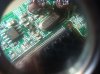
This Sony has a burnt chip or SMD device on the main board. The code on the chip is NEQ2 and the location ID on the board is U202.

Thinking "U" stands for an IC chip, I have been unable to ID it to replace it.
I can remove and replace the SMD chip if I can get another or clone. I followed the ID line to an transistor ID but with a U202 board location a transistor should not replace it.

Can anyone help?

Thanks
 

Attachments

  • 004.JPG
    004.JPG
    1.9 MB · Views: 141
A 3-pin device has a good chance of being a transistor or voltage regulator. Other choices include dual diodes with a common pin. It is surrounded by capacitors; although, I can't trace what they go to. I would lean to it being a voltage regulator.

Is it the only 3-pin device with a "U" identifier? Are there other 3-pin devices with Q (or something else) identifiers?
 
Welcome.
Pissed off with the multitude of websites giving misleading garbage when looking for service/schematics, yielding truncated information, looking to spam you, inject advertisements, obtain email, or infecting the computer.
The parts list and schematics not included here : ----> https://servicemanuals.us/sony/monitor/sdm-hs75-sdm-hs75d-sdm-hs75p.html

There may be other correct sites, try your luck to identify U202. Could not find the schematics nor parts list at the Sony support site.

Did find a good schematic for different model SDM-HS74P but there is no U202 in it. :-(
The schematic is necessary to discern why U202 failed. Replacing it may blow again.
 
Last edited:
A 3-pin device has a good chance of being a transistor or voltage regulator. Other choices include dual diodes with a common pin. It is surrounded by capacitors; although, I can't trace what they go to. I would lean to it being a voltage regulator.

Is it the only 3-pin device with a "U" identifier? Are there other 3-pin devices with Q (or something else) identifiers?

The only other "U***" code is next to 8 and 14 pin devices.
Looking at the board, could the U202 be the location of the metal device below the code and the R250 code above the bad device be the correct code?
If the photo is not good enough I try a better pic.
 
No, the metal device near U202 is a crystal oscillator and its code is X201 ("X" is often used for crystals). R250 would be a resistor. Your burned device is not a resistor.

The difficulty seeing the traces is not the picture. They are just hard to see. Here is how a typical 3-pin voltage regulator is connected:
upload_2017-12-9_11-45-13.png


Pin assignments can vary. Here is one arrangement:

upload_2017-12-9_11-46-19.png


See if any of the surrounding capacitors are connected directly to the pins and to ground. One pin should be to ground or to a resistor. Your pin numbering should be the same. That is, the pin on the side by itself is pin 3. But, the functions of the pins can be different.
 
Welcome.
Pissed off with the multitude of websites giving misleading garbage when looking for service/schematics, yielding truncated information, looking to spam you, inject advertisements, obtain email, or infecting the computer.
The parts list and schematics not included here : ----> https://servicemanuals.us/sony/monitor/sdm-hs75-sdm-hs75d-sdm-hs75p.html

There may be other correct sites, try your luck to identify U202. Could not find the schematics nor parts list at the Sony support site.

Did find a good schematic for different model SDM-HS74P but there is no U202 in it. :-(
The schematic is necessary to discern why U202 failed. Replacing it may blow again.

For about a week now I've been to what seems like a thousand web sites looking for information about the NEQ2 on a U202 location and the only sites that had a like main board was Russian, some other videos talking in some other than English.
I did find the Sony service manual several days ago and it even talks about how to identify and re-solder devices on the boards during repair but it did have any schematics or information about the components of the boards.

My wife like crossword puzzles, I like circuit design, tech manuals, topo and aerial flight maps and thing that are hard to understand. I enjoy the mystery.
 
...could the U202 be the location of the metal device...
The metal device is a crystal labeled as X201

Check if U202 pins traces go to U203 or to the large IC with heatsink.
Then look for the application notes of the pertinent one to attempt finding what U202 does. Attempt drawing a schematic of U202 vicinity.

Did you remove R250 or it removed itself on a explosion ?
 
Last edited:
The metal device is a crystal labeled as X201

Check if U202 pins traces go to U203 or to the large IC with heatsink.
Then look for the application notes of the pertinent one to attempt finding what U202 does. Attempt drawing a schematic of U202 vicinity.

Did you remove R250 or it removed itself on a explosion ?


Using the sot-23 drawing above, the #3 and #1 post shows a ground, the 2 post shows open to ground.

The #3 and #1 shows a short to several pins on the U201, The top right U201 closest to the bad chip, pin 1 and 2 gets s ahort beep pin 3 or the third pin down show s short to ground.
On R250 the empty top post shows short to ground eth bottom post gets just a beep. It may be empty like R217. I don't think a resister was in R250, since the lower solder is still a clean ball.
You can clearly see the black plastic has over heated on NEQ2, some black flowed out on to pin #3.
Does U202, supposed to have a hard short to ground on 3 and 1 while the board is not powered up?
 
A voltage regulator (or transistor) will often have one pin a dead short to ground. Shorting another of its pins to ground (e.g, the output) may be why it failed.

See if you can trace out where those 2 pins go. An intended ground may be to a large "ground plane." A fault to ground would not show an obvious connection to the ground plane. Connection to a capacitor will show a open, but it may show an initial connection that then "opens" as the capacitor charges up.
 
Remove U202. If its GND pin is shorted internally to its out + not-grounded pin, you will find many grounded spots that are meant to be not-grounded +.

Is U201 the large IC ?
Removal of U202 will allow better visual on traces to prepare a schematic sketch. And confirm the grounded pins found at U201 are not grounded any more.
Still believe you must check U201 application data sheet. Will tell which are supposed to be +, which GND

If U202 was a V reg, one pin should be GND; one pin should have continuity to an electrolytic capacitor +, one pin feeding regulated voltage to U201.
 
Welcome.
Pissed off with the multitude of websites giving misleading garbage when looking for service/schematics, yielding truncated information, looking to spam you, inject advertisements, obtain email, or infecting the computer.
The parts list and schematics not included here : ----> https://servicemanuals.us/sony/monitor/sdm-hs75-sdm-hs75d-sdm-hs75p.html

There may be other correct sites, try your luck to identify U202. Could not find the schematics nor parts list at the Sony support site.

Did find a good schematic for different model SDM-HS74P but there is no U202 in it. :-(
The schematic is necessary to discern why U202 failed. Replacing it may blow again.
Where did you find the SDM -HS74P schematic?
 
It appears to be a reset power switch. Could be a random failure or due to a voltage surge, but it also could have acted as a fuse for something downstream that drew too much current..

Here's a post with the same problem (do you happen to be Polish?): https://www.elektroda.pl/rtvforum/topic2496338.html


I found this one too last week but I never noticed the translate option. I believe it is the exact same problem as mine, but he ID'd the chip but it didn't make sense to me then. I have learned a lot since I started with this project.
 
I believe I just ID'd the part in question

PARTS#: EM6353BX1SP3B-4.6

BRAND: EM MICRO

PACKAGE: SOT23

DESC: 4.6V Reset IC with Fixed Delay

I'm ordering a set.

Thanks for all the help, y'all have made the search to solve the mystery enjoyable.
 
Things like that may fail because of a more serious problem downstream. Be sure to order two or three.
 
The only ones I could find tonight is a pack of 4 from Taiwan.

I ran trouble on POTS lines for 30 years, 15 of those were ISDN and DSL and fiber optics. When everything works as it should, life is boring. Troubleshooting and locating failures became a way of life for me before retiring.

I enjoy electronics, always have. the part of working I miss is being a, "Irate Customer Contact." When customers demanded a supervisor come to their home or business, and would talk to anyone over the phone, the company would call me.
I got jumped on, dumped on, and called every name in the book about their communications problem. The thing that made the job fun was 90% of the time the problem was the customers on faults.

Talk about crawling back groveling out from under the rock. But 10% of the time I have to just stand there and listen before the customers would end their venting of their trouble.
 
The equivalent part is MAX809, perhaps less difficult to find.

That U202 supervisory chip resets the microcontroler after power is sensed good at powerup. Being fully shorted should not have damaged the microcontroller U201 as its reset pin would only be +Vcc, same as 'not reset' condition.
What I would do is remove U202 from the board, turn it on and after probing Vcc to have a valid voltage, then ground the reset trace that was connected to U202 pin 2 to turn the monitor on.
In other words, if power Vcc is measured healthy, ground pin 2 trace firmly to pin 1 trace and the monitor should resurrect. Have video in when doing that.
'Healthy' means well filtered, no spikes and steady. If an electrolytic went kaput causing all this; replace first.

upload_2017-12-11_19-58-26.png


upload_2017-12-11_20-2-34.png
 
Last edited:
Status
Not open for further replies.

Latest threads

New Articles From Microcontroller Tips

Back
Top