Ahhh... OK, I get the concept now, though I do not understand the reasoning for doing it that way?I can't see how it's messed up. My code is outputting a pulse of 1 to 2 mS every 2.5mS to give a total time of 20mS. The servoTemp=0; is required to output the gap between pulses.
Actual RC gear traditionally used literal shift register decode, with newer stuff doing it in software.
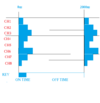
The servo pulses follow each other directly as a "1" is shifted through the SR by timed pulses received from the TX. The frame gap resets a timer and sets the SR input high until another pulse is received.
I've used my version numerous times with both standard and ultra high precision robotics servos with no jitter problems at all, as long as power and grounds are good & well decoupled. It could be very simply modified for a fixed overall frame duration if required.
If there are problems with jitter from the Oshonsoft version software, it may be that the BASIC runtime is using & blocking interrupts, possibly a timer for it's internal functions?
This is info from a current model 2.4GHz digital system - no difference in timing from my 1970s analog gear: