Continue to Site

Welcome to our site!

Electro Tech is an online community (with over 170,000 members) who enjoy talking about and building electronic circuits, projects and gadgets. To participate you need to register. Registration is free. Click here to register now.

  • Welcome to our site! Electro Tech is an online community (with over 170,000 members) who enjoy talking about and building electronic circuits, projects and gadgets. To participate you need to register. Registration is free. Click here to register now.

Graphic LCD 96x64 w/ SED1565 Controller

Status
Not open for further replies.
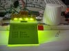
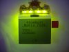
These are very cool. And cheap. And work! lol

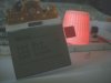
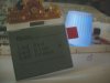
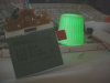
i have yet to test the temp sensor. It has a button also. The speaker isnt there tho. It has the 2 cirlcles in the middle tho as the connection. Remember this was from a CELL PHONE so im sure the speaker for it would be too small anyway. But you can use the connection as a button if you have a old cell phone and take out the little buttons with that tape on it and place it there. Ill take a picture on how to tomorrow.
 
dude bad news!!!

I tried to make a set pixel command and noticed along the way that since im setting 1 byte at a time and not indiviual pixels that i need to read the old value on the GLCD then OR it with new value to make it look like its setting pixels. Because if i dont i might mistakenly clear a black/on pixel.


EDIT:
More bad news. I need to trace these pinout If i wish to read the GLCD.

A0 = PIN 4 (D/C)(display or control) aka (data or command)(user controlled)
RD = No PIN (data bus is in an output status when this signal is “L”. H = input)(i think pulled high)
WR = No PIN (When R/W = “H”: Read. L = Write)(I think pulled low)
 
Last edited:
Where's the IC for the display? You never posted a picture of the other side of the board.
 
Heh here is the back:
 

Attachments

  • ECM-A0997-2-BACK.jpg
    ECM-A0997-2-BACK.jpg
    43.1 KB · Views: 344
I made altered the text function to underline and strike through text. Of course you can do both at the same time if you wish :D
Here is the code... also it can now take different font sizes. I have 2-8x8 fonts and 1-5x7 font.
Code:
void LCDString(rom unsigned char *str, unsigned char myFont, unsigned char fade, unsigned char typed, unsigned char style){
	char x;
	char y;
	char fontSize,orWith;
	char MyData;

	switch(myFont){
		case 1:
			fontSize = 8;
			break;
		case 2:
			fontSize = 8;
			break;
		case 3:
			fontSize = 5;
			break;
	}
	switch(style){
		case 'u':		//underline
			orWith = 0x80;
			break;
		case 's':		//strikes
			orWith = 0x10;
			break;
		case 0x00:
			orWith = 0x00;
			break;
	}

	while(*str != 0){
		y = *str++;
		y -= 0x20;

		for(x=0;x<fontSize;x++){
			if(myFont == 1)
					MyData = FontA[y][x] | orWith;
			if(myFont == 2)
					MyData = FontB[y][x] | orWith;
			if(myFont == 3)
					MyData = Atom5x8[y][x] | orWith;

			LCD_Send(MyData,1);

			if(fade > 0) 
				Delay1KTCYx(fade);
		}
		if(typed > 0)
			Delay10KTCYx(typed);

	}
}
Here it how it looks:
 

Attachments

  • undersrike.jpg
    undersrike.jpg
    43.3 KB · Views: 360
I see hot glue melted over the connecting wires to hold them in place. How did you connect the wires - soldered to the lcd connector, or did you plug a breakout board with the matching connector?
 
VISN:
soldered :D nice observation. I wish i had a breakout :D

Mr RB:
Yeah i know :D i was trying to create my own but as you can see im not that good at font creation :)

you know of a good 5x7 Font already made?

The issue is i scan fonts from top to bottom and left to right like ad would be:
11111100
10000010
10000001
10000001
10000010
10000100
11111000

The first hex is 0xFF and a total of 5 Bytes for me, most fonts are from LEFT to RIGHT then TOP to BOTTOM so most would have a 0xFC instead and be 7 bytes long.
 
heh was bored:
(This video is still being processed. Video quality may improve once processing is complete. )
[embed]http://www.youtube.com/v/hv3LRuQ0Qkw[/embed]
 
Last edited:
Alrighty smarty. Lets see a program which lets you vary all three values with at least 8 levels per colour =)

By the way, if there's a user of the year award ever given away here, I think your in the running. Between the code, the excellent schematics and the video results it's all top notch posted right there for everyone to see. Good stuff.
 
heh Thanks a bunch! i would be happy just to be in the running :D

I dont do PWM lol hate trying to do 3 at a time arg.. i get lost.. maybe because all my pics have 2 hardware only and the third would have to be in software

Im going to clean up the code for the menu. Its a mess :D
 
Last edited:
Jason,

1) The photos might look a little clearer if you removed the protective film.

2) Have you confirmed the resolution?

--David
 
I wouldn't touch that protective film until it's in a unit to be used. Mike2545 sent me a butterlfy a ways back, the protective cover is still on it.
 
I would never remove the protective film. I might be smart but im a messy guy lol
it would be unreadable if i had removed it lol

Yes I can fit :
12 (x 8 bits = 96 pixels) letters on screen from left to right and
8 (x 8 bits = 64 pixels ) down from top so thats 96x64.

The only wierd thing is the pixels on the left start at 18 aka 0x12. But its still 96 pixels from there on.

Here is my code for the menu. Its not the best coding but works like a charm. Even include a last menu to turn off leds and hide arrow on screen. Ill take a picture of the 4 stages.

Code:
void UpdateMenu(void){
	unsigned char leftL, leftH, topV,x;
/*
	char left = 104;		//88 + 18 = 104 //I add 18 becuase the LCD starts on pixel 18 not 1

	leftH = left >> 4;	 	//Calculate The Left Pixel
	leftH |= 0x10;   		//Get upper byte in LeftH OR with 0x10 to prodcuce a valid command
	leftL = left & 0x0F; 	//Get lower byte in LeftL
//  Older Code remove with next 2 lines
*/
	leftH = 22;					//Since this is a constant value i did the math 
	leftL = 8;					//to save some time and placed it here
	
	topV = 0xB0 + Top_POS;		//Get the Top position and add 0xB0 to set the row (TOP)

	if(Menu_POS > 3) {			//If in Item 4 aka 0 erase arrow on 3
		LCD_Send((topV-1),0);	//Send Top Position - 1 this way we get the arrow on 3
		LCD_Send(leftH,0);		//Send Upper Left Position
		LCD_Send(leftL,0);		//Send Lower Left Position

		for(x=0;x<8;x++)		//Clear the arrow by setting to all 0's
			LCD_Send(0x00,1);

		Menu_POS = 0;			//Clear the Menu Position
		Top_POS = Top_STA;		//Reset the Top Start
	}
	
	if(Menu_POS > 0){				//If item is greater than 0 do below
		if(Menu_POS > 1){			//If in Item 2 erase arrow on 1 or 3 erase arrow on 2
			LCD_Send((topV-1),0);	//Send Top Position
			LCD_Send(leftH,0);		//Send Upper Left Position
			LCD_Send(leftL,0);		//Send Lower Left Position

			for(x=0;x<8;x++)		//clear the old arrow
				LCD_Send(0x00,1);
		}

		LCD_Send(topV,0);		//Send New Top Position
		LCD_Send(leftH,0);		//Send Upper Left Position
		LCD_Send(leftL,0);		//Send Lower Left Position

		for(x=0;x<8;x++)		//Send out our arrow which is added to the FontA and FontB
			LCD_Send(FontB[96][x],1);
	}

	switch(Menu_POS){			//This is the actual command to set the LEDs
		case 0:
			LATB = 0b00000111;	//Common Anode so to turn on i need Logic Low to turn on led.
			break;
		case 1:
			LATB = 0b00000110;
			break;
		case 2:
			LATB = 0b00000101;
			break;
		case 3:
			LATB = 0b00000011;
			break;
	}
}

Im calling it like:
Code:
	while(1){
		if(button == 0){
			Menu_POS++;
			Top_POS++;
			UpdateMenu();
			Delay10KTCYx(100);
		} 
	}
 
Last edited:
Jason,

I thought maybe there were actually 65 pixels.

The pixels are offset to simplify the controller/LCD connection. I've seen that before.

--David
 
Just noticed pictures wont show my LED Color. So i took off the flash lol and here ya go from left to right is Menu items 0-3:
 

Attachments

  • 1.jpg
    1.jpg
    26.4 KB · Views: 294
  • 2.jpg
    2.jpg
    25.4 KB · Views: 274
  • 3.jpg
    3.jpg
    29.3 KB · Views: 252
  • 4.jpg
    4.jpg
    25.8 KB · Views: 260
Graphic LCD 96x64 w/ SED1565 Controller connector

Hi everybody,
Does anyone know where to find the connector for these LCD's.
Thank you.

Geraldes
 
heh would you believe there isnt one ? i dont but i doubt there is one. I think it was pushed against the PCB and held there.

Im designing a board and holder right now in 3d studio max (3D CAD software) to hopefully get it produced as a board so i can stock em and sell em.

Im make a rough draft drawing now.
 
Looking at the pictures, it's an FPC connector of some kind. It doesn't look standard though, since the FPC seems to extend to the left and right even when the contacts stop.

I ordered a few of the E-Bay $1 ones. I really don't have a specific use right now, but I'm thinking maybe add it to an RF remote with an MSP430 and a CC1100 low power RF transceiver. It'll give much better visual feedback on controlled devices and use very little power for a battery operated device.
 
Status
Not open for further replies.

New Articles From Microcontroller Tips

Back
Top