MrDEB
Well-Known Member
going to visit my daughter in Vancover Washington in September and need a project to build (for 4 year old grandson) as I get up at 4am each morning so need something to do.
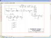
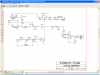
Was going to build a more complex Theremin but this small unit will work just fine.
**broken link removed**
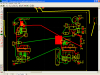
adding a LM386 amp and etching a circuit board
just curious about the amp section = looks right but ??
Audioguru would have a field day with this circuit.
I want to implement some day a PIC using ADC, maybe several PICs for a simulation of a 5 string guitar using photodiodes on the neck for the different tones.
just kidding about grandparent revenge but it sounds good.
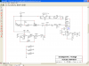
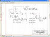
Was going to build a more complex Theremin but this small unit will work just fine.
**broken link removed**
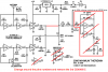
adding a LM386 amp and etching a circuit board
just curious about the amp section = looks right but ??
Audioguru would have a field day with this circuit.
I want to implement some day a PIC using ADC, maybe several PICs for a simulation of a 5 string guitar using photodiodes on the neck for the different tones.
just kidding about grandparent revenge but it sounds good.