briguy280z
New Member
Hi all i am new to the forum and looks to be a
long time member!!! Lots of good info
here...Otherwise heres my project
Background
I am a 280Z car enthusiast and i am doing a
farly difficult convertion. I am placing a LS1 GM
Engine into a Datsun 78 280Z. The car is just about
done but for a few electronic issues. I created two
circuits so far for this car.
A PCM Vats Simulator. 5V 40Hz 50% duty cycle
square wave --Works Great!!
This is the one I need help with.
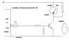
**It is a GM fuel tank sender to Datsun Fuel Guage convertion
What I have to work with is a .39V (LOW) to 2.9V (FULL)
sending voltage from the sending unit. The Guage uses
a 3V (LOW) to 6.5V (FULL) as operation voltage. What
i did sofar is designed a circuit that uses two 741 Opamp's.
The first is used as a summer and the second as a amplifier.
I have simulated it in EWB and seems to work!
First Problem!!!
I will need to supply the circuit with a +12V to -12V.
That would mean i would have to create a AC converter and
then convert to DC again....any other ideas??? Will it still work
with 12-0V????
Second Problem!!!
The guage requires 50mA I dont think the circuit can handled this!
My power supply with the regulator really gets hot when I have it
direct connected. I was told that I could use a JFET to get this kind
of current...I dont know how that works!
If a picture would help let me know and i will upload it to my
website and post it!
Thanks for any help i can get!
long time member!!! Lots of good info
here...Otherwise heres my project
Background
I am a 280Z car enthusiast and i am doing a
farly difficult convertion. I am placing a LS1 GM
Engine into a Datsun 78 280Z. The car is just about
done but for a few electronic issues. I created two
circuits so far for this car.
A PCM Vats Simulator. 5V 40Hz 50% duty cycle
square wave --Works Great!!
This is the one I need help with.
**It is a GM fuel tank sender to Datsun Fuel Guage convertion
What I have to work with is a .39V (LOW) to 2.9V (FULL)
sending voltage from the sending unit. The Guage uses
a 3V (LOW) to 6.5V (FULL) as operation voltage. What
i did sofar is designed a circuit that uses two 741 Opamp's.
The first is used as a summer and the second as a amplifier.
I have simulated it in EWB and seems to work!
First Problem!!!
I will need to supply the circuit with a +12V to -12V.
That would mean i would have to create a AC converter and
then convert to DC again....any other ideas??? Will it still work
with 12-0V????
Second Problem!!!
The guage requires 50mA I dont think the circuit can handled this!
My power supply with the regulator really gets hot when I have it
direct connected. I was told that I could use a JFET to get this kind
of current...I dont know how that works!
If a picture would help let me know and i will upload it to my
website and post it!
Thanks for any help i can get!
 I am posting the