Continue to Site

Welcome to our site!

Electro Tech is an online community (with over 170,000 members) who enjoy talking about and building electronic circuits, projects and gadgets. To participate you need to register. Registration is free. Click here to register now.

  • Welcome to our site! Electro Tech is an online community (with over 170,000 members) who enjoy talking about and building electronic circuits, projects and gadgets. To participate you need to register. Registration is free. Click here to register now.

Giant cylindrical color organ/VU meter for a nightclub

Status
Not open for further replies.
OK i made a schematic to kind of show what im talking about.

You see the blue LED signal come in off the arduino to what would be LED row number one, then the diode drops the voltage by ~.7V and takes it to LED row number 2. Then another diode drops the voltage and takes it to LED row number 3. I would then repeat this for green and red.

Can someone please verify that im on the right track here?

https://123d.circuits.io/circuits/865584-the-unnamed-circuit
 
Your link does not work. Please attach your schematic HERE to your reply here.

An LED sets its own voltage, it is driven with a certain amount of current, so your diodes idea will not work. A blue LED operates at about 3.2V to be very bright and if you reduce the voltage 0.1V then it will be off or very dim. A diode will reduce the voltage fed to it of 0.7V to only about 2.5V so the LED will produce no light.
Half the current dims it only a little because our vision (and hearing) have logarithmic sensitivities. I think 1/10th the current makes the light look half as bright.
 
Attach my schematic where? Where is HERE? This site doesnt seem to let me download the thing, only embed it.

It really looks like thats this guy got his to dim on his instructable. He talks about how the diode removes the .7V and that decreases the brightness of each subsequent section. Im totally lost now.
 
This site doesnt seem to let me download the thing
Use the 'Upload a file' button at the foot of the reply box. Please keep the file size to a minimum (e.g. ~300k or less).
 
Hello mjkelly93. I've uploaded your schematic to ETO.

When a site doesn't allow you to download the schematic, you can take a photo of it using the Impr Pant / Pet Sis key on your keyboard (Is located at the right top border of your keyboard). After pressing the key you can paste the image on Microsoft paint, or your favorite drawing program.

I suggest you to re-order the elements of your design and connect all the loose pins. At this point it makes no sense and forum members will not be able to help you.

sc1.png sc2.png
 
Ahhhhhh ok thank you menticol. I didnt think of a screen shot.

Let me mess around with it a little more i just wanted to demonstrate the concept of dropping the voltage from 1 line to the next with the diodes.
 
OK instead of writing up the entire circuit, i decided to make it much more simpler just to ask my question.

The audio signal has left the MSGEQ7 and been processed through the Arduino. Now in the picture, the arduino is putting out the blue signal to the transistor controlling the blue circuit for the strip light. The other transistors are there for the next line of lights which needs to be dimmer than the previous one.

What i think i need to do, to make this work properly, is to lower the signal that the arduino is sending that first transistor by a standard amount for each other transistor. So if the voltage coming in to blue is 3V, i need to lower that by .1V-.3V to the next transistor, and then another .1V-.3V to the next transistor and so on.

What can i put inline from the first transistor to the second transistor and so on to lower the voltage by a set amount each time? Im thinking i can just tinker around with different sized components until i can get it perfect so it looks great.
 

Attachments

  • simple circuit.jpg
    simple circuit.jpg
    329.5 KB · Views: 166
Why are you lowering the voltage by a set amount? I missed the reasoning.
Is it something the Arduino could do in the digital domain?
 
Possibly but im not sure. If it can, i havent read it about it anywhere so i was following this persons instructable doing it with components rather than a processor.

This is the video im trying to replicate where you can see each line getting less voltage. He says he did this with a 1n4148 diode inbetween each transistor dropping the voltage a set amount each time but Audioguru is telling me it cant be done like that so now im a little lost.


Im going to try and build something like this except 3' wide, 10 foot high, and a cylinder. It will light from the middle and work its way out like this video. The levels will be 10" wide plexiglass sheets with LED's perpendicular to them sort of like how my columns i built in the other video i posted of my other bar. It starts at about 40 seconds.

 
I was rereading through the thread and i figured it cant hurt to put the code up here so here it is:


/* David Wang
* Code that takes audio input from a 3.5mm cable
* and flashes an LED strip based on the frequency
* of the music.
*
* HUGE thanks to the arduino community
* If you see your code here, I owe you my gratitude
*
*/

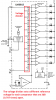
int analogPin = 0; // MSGEQ7 OUT
int strobePin = 2; // MSGEQ7 STROBE
int resetPin = 4; // MSGEQ7 RESET
int spectrumValue[7];

// MSGEQ7 OUT pin produces values around 50-80
// when there is no input, so use this value to
// filter out a lot of the chaff.
int filterValue = 80;

// LED pins connected to the PWM pins on the Arduino

int ledPinR = 9;
int ledPinG = 10;
int ledPinB = 11;

void setup()
{
Serial.begin(9600);
// Read from MSGEQ7 OUT
pinMode(analogPin, INPUT);
// Write to MSGEQ7 STROBE and RESET
pinMode(strobePin, OUTPUT);
pinMode(resetPin, OUTPUT);

// Set analogPin's reference voltage
analogReference(DEFAULT); // 5V

// Set startup values for pins
digitalWrite(resetPin, LOW);
digitalWrite(strobePin, HIGH);
}

void loop()
{
// Set reset pin low to enable strobe
digitalWrite(resetPin, HIGH);
digitalWrite(resetPin, LOW);

// Get all 7 spectrum values from the MSGEQ7
for (int i = 0; i < 7; i++)
{
digitalWrite(strobePin, LOW);
delayMicroseconds(30); // Allow output to settle

spectrumValue = analogRead(analogPin);

// Constrain any value above 1023 or below filterValue
spectrumValue = constrain(spectrumValue, filterValue, 1023);


// Remap the value to a number between 0 and 255
spectrumValue = map(spectrumValue, filterValue, 1023, 0, 255);

// Remove serial stuff after debugging
Serial.print(spectrumValue);
Serial.print(" ");
digitalWrite(strobePin, HIGH);
}

Serial.println();

// Write the PWM values to the LEDs
// I find that with three LEDs, these three spectrum values work the best
analogWrite(ledPinR, spectrumValue[1]);
analogWrite(ledPinG, spectrumValue[4]);
analogWrite(ledPinB, spectrumValue[6]);
}
 

Attachments

  • arduino_ino.ino
    2 KB · Views: 145
A resistor in series with an LED converts a voltage signal fed to them into a current signal that controls the brightness of the LED. If you want LEDs to flash to the music but each LED to be dimmer than the previous LED then each input to the LEDs probably from a transistor can use a voltage divider (not a diode) to reduce the sensitivity of the LED/transistor.
 
Thats the answer i was looking for. A voltage divider huh. Im gonna look that up because i never heard of one before. Any idea what kind of voltage divider i should be looking for? Are there different ratings?
 
Thats the answer i was looking for. A voltage divider huh. Im gonna look that up because i never heard of one before. Any idea what kind of voltage divider i should be looking for? Are there different ratings?
Two resistors divide a voltage. A bunch of series resistors make a voltage divider with many voltages like is used in the LM3915 bar graph driver that I used in my sound Level Indicator project.
The LM3915 drives 10 LEDs showing the level of the input signal. My project has a peak detector but the datasheet says if you simply apply the signal directly to the input of an LM3915 then it will show instantaneous levels allowing the peak and average levels to be seen. You want high levels to produce bright light and low levels to produce dim light and then the LM3915 without a peak detector might do it (I have never tried it). The very sensitive comparator will turn on its LED most of the time and it will be bright. Comparators that are not sensitive will turn on their LED for only part of the signal and will be dim.
Here is a part of the LM3915 datasheet showing the voltage divider:
 

Attachments

  • LM3915 voltage divider.png
    LM3915 voltage divider.png
    59.8 KB · Views: 171
I looked at the LM3915 since its used in a ton of VU meters on youtube. I decided against it but now im reconsidering a little.

Can i redirect each color output, red green and blue, from the arduino through the three separete LM3915 then onto the LEDs? Or does the LM3915 only work with a direct audio input?
What are the outputs from the Arduino? Aren't they filtered audio for bass, midrange and highs? Then they feed directly into the input of each LM3915.

The maximum LED supply for the LEDs on an LM3915 is 25V so each output can easily drive striplight LEDs in series.

Have you tested an LM3915 with audio to see if it produces the range of brightness you want? Is the maximum output current of 30mA bright enough?
 
The input to the arduino is the signal from the MSGEQ7 splitting the signal into 7 bands. The arduino then takes 3 of these 7 bands and converts them into voltage for the colors. In the case of the code above, red is the low, green is the mids, and blue is the highs using spectrum values 1, 4, and 6. Then those signals, for the red green and blue, is output each corresponding to its own transistor then on to the LED strip as each individual color on the strip.

No i havent tested out an LM3915. I ruled it out because it wouldn't split the signal into the colors i want like the arduino would. What im thinking now is that instead of using voltage dividers to get the voltage down before the transistors, perhaps i could use 3 LM3915 chips, one for each color utilizing the 3 outputs the arduino. Maybe i could put something inline between the output from the arduino and the LM3915 to adjust the brightness of the LEDs like a potentiometer?

I just ordered some potentiometers and LM3915s.
 
The LM3915 has the maximum brightness adjusted by the amount of current to ground from its reference voltage at pin 7. The duty-cycle of the audio determines how much dimming there will be. A loud signal turns on the low level comparator most of the time and a low level turns on the high level comparator for only a portion of each cycle.
 
Adjusting the voltage fed to an LED simply burns it out. An LED sets its own voltage and its current and its duty-cycle determine its brightness.
Without a peak detector then the LED is flickering with every single cycle of the music frequencies. Our vision sees fast flickering as being steady continuous light but the duty-cycle sets the brightness.
Narrow pulses and a dim LED is produced when the music is not loud because the output transistor turns on only for the narrow tip of each cycle. Loud sounds turn on the transistor for almost the entire cycle producing wide pulses that cause the LED to appear bright.

But an LM3915 IC drives 10 LEDs and lights one or none when the music is not loud and lights all of them when it is loud. During loud sounds then the low level LEDs are lighted almost continuously which makes them appear to be bright.
 
This website locked up again during my reply and it seemed that my reply did nothing so I hit the post button over and over until it showed all my duplicated posts.
 
Status
Not open for further replies.

Latest threads

Back
Top