Continue to Site

Welcome to our site!

Electro Tech is an online community (with over 170,000 members) who enjoy talking about and building electronic circuits, projects and gadgets. To participate you need to register. Registration is free. Click here to register now.

  • Welcome to our site! Electro Tech is an online community (with over 170,000 members) who enjoy talking about and building electronic circuits, projects and gadgets. To participate you need to register. Registration is free. Click here to register now.

Gate Opener Idea

Status
Not open for further replies.

Iawia

Member
Hi All,

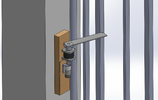
I am attempting to open a driveway gate with a 24v motor amplified by a 10:1 gear train to get me to 500 kg-cm of torque. I was told I needed an H-bridge for the bi-directional motor control. The motor stall current is 3A, so most motor drivers I have seen can do up too 2.6 continuous current, 3A transient current, so I guess these drivers will not work.

My questions regarding this setup are:

1) I was looking at this controller (https://www.sparkfun.com/datasheets/Robotics/L298_H_Bridge.pdf). What were to happen if the motor exceeded 3A maximum? Does this destroy the controller or does the controller sense this problem and loop out? What precautions can be done to ensure the controller never goes above 2.6 A continuous? I assume i cannot use this since my motor stall current is 3A.

2) I found a controller that can do more than 3A (Jrk G2 24v13A) but it is a hefty $140. Before I make this purchase I want to discuss with y'all regarding this! (I still want to shut down if amperage gets out of control here and i'm not sure how too do that).

I will use a raspberry pi to provide the logic to the controller and eventually RF control. I am just a knowledgeable hobbyist so I feel quite inadequate when it comes to circuits. Any recommendations or assertions you can provide regarding my general mechanical or electrical assembly are welcome.

13 Amp Mtr Controller
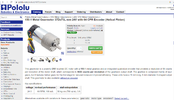
37D 150:1 Gear Motor

Thank you! You guys are the best.

ps. I will add a chain to the end of the armature to pull the gate closed in clockwise operation. Counter clockwise operation, the arm will push the gate open.
 

Attachments

  • ISO view.png
    ISO view.png
    293.4 KB · Views: 158
  • Motor, Pololu 37D, 150_1.png
    Motor, Pololu 37D, 150_1.png
    314.8 KB · Views: 179
  • Jrk G2 24v13A USB Mtr Ctl.png
    Jrk G2 24v13A USB Mtr Ctl.png
    273.8 KB · Views: 159
How about this bridge driver.
It's rated for 3A and uses MOSFETs instead of BJTs so it has much lower power dissipation than the L298 device, thus it doesn't require as large a heat sink, and it also has overcurrent protection.
 
Hi crutschow, this looks exactly like what I need. Upon reading the data sheet, I cant seem to find my footing with the electro-speak. It refers to M1-M4, am I trying to form a pulse with these wires? Page 15 of the datasheet shows a typical stepper motor application, but since my motor is a brushed 24V DC motor would i simply eliminate the bottom half?

Will keeping the suggested resistors and capacitors get me the overcurrent protection?

1667955847591.png
 
Upon reading the data sheet, I cant seem to find my footing with the electro-speak.
Yes, data sheets can be a little imitating at times.
The Application circuit you mentioned is for a 2-phase chopper driver, which you are not doing.
You application just requires a steady application of voltage in either direction.
The basic motor circuit connection is shown below.
The motor direction is controlled by the Direction Pin 11.
Connect the Brake Pin 10 to signal ground.

1667960639009.png


The current limiting setting is as shown in Table 1 and Figure 12.
D is the 4-binary input to the control DAC, so for a 3A limit you would set the 4 inputs to 5V and use an Rs of 6.25kΩ (and add 500pF across Rs).
Note that you need a 5V supply for the DAC reference (pin 14) and the DAC control pins (possibly from the Raspberry Pi supply?)

Bypassing the supply is necessary as this from the data sheet states:
Bypassing the power supply line at VCC is required to protect the device and minimize the adverse effects of normal operation on the power supply rail. Using both a 1 μF high frequency ceramic capacitor and a large-value aluminum electrolytic capacitor is highly recommended. A value of 100 μF per ampere of load current usually suffices for the aluminum electrolytic capacitor. Both capacitors should have short leads and be located within one half inch of VCC.

The SGND should go to the Raspberry ground, and the PGND to the motor supply ground with them tied together near the module pins.

The device should be mounted on a small heat-sink to prevent overheating (with a thin layer of thermal grease between the mounting tab and the heat-sink.

Any other questions, let us know.
 
Last edited:
Hi crutschow, thank you for this information. Based on your assistance, I have drawn up the schematic as follows:

1667969676270.png


Does this look correct to you? To drive the motor, I would set all the 'M1-M4' pins to HIGH, and LOW to turn off the motor? As for the brake, I assume I would add a 1k pull up resistor just before ground on pin 10 for an emergency brake? Just checking.

The CS Out pin, does it need to be connected to anything? What is it for? I cant seem to understand the 3 Rc circuits, and why they are needed, but I am VERY happy that at least I can get the project off the ground!
 
Does this look correct to you? To drive the motor, I would set all the 'M1-M4' pins to HIGH, and LOW to turn off the motor?
I missed needing to turn the motor on and off.
That can best be done with the Brake Pin 10 set to 5V for OFF and 0V for ON.
You can leave M1-M4 connected to 5V at all times.

Otherwise looks OK.
The CS Out pin, does it need to be connected to anything?
You have it connected to the 6.25k resistor and capacitor, which is correct.
Don't understand why you asked that question(?).
cant seem to understand the 3 Rc circuits, and why they are needed,
The RC circuit at the monostable output determines the time the current is shut off to the motor when an overcurrent is detected, before it is turned back on.

The RC circuit at the CS Out is part of what determines the current limit.

What's the 3rd RC circuit?
 
With a stall current of 3A it probably has a run current of ~1A so a total power of ~24W. This seems a little small for the task. Anyone any experience with the size of motors normally used for this?

Mike.
Edit, agree on the relays, much simpler.
 
Can I get the bidirectional control with relays? What about the overcurrent protection?

If I wanted speed control for this brushed DC motor, would I set the M1-M4 pins between 0000 and 1111 to get the speed control (1111 being the highest speed)?

Hi Pommie I also question the motor size. I did a calculation based on pulling scale on the gate with a string to see the force required, then measured the distance to the hinge. The max torque was ~500 kg-cm including rough transients forces. Hence the 37D motor by itself will produce 56 kg-cm @3A MAX. When put through the gear I will get 10X the torque at 10X speed reduction (which is ok, ~3RPM). I admit I have never done an application like this, but the numbers check out. With a 10% efficiency loss at the gear, we get 504 kg-cm. I can go for a 20:1 ratio gear to get me 20X torque (~1000 kg-cm), but I would be at ~1.5 RPM. But I am definitely open to changing the motor. I didn't want to sacrifice too much speed if I didn't have too.

crutschow I meant the COMP Out which is not connected at the moment.
You have it connected to the 6.25k resistor and capacitor, which is correct.
Don't understand why you asked that question(?).
Thank you guys for your help!
 
Can I get the bidirectional control with relays?
Yes, you use two SPDT relays in an H-bridge configuration.
Basic circuit below:

Edit: Here's an example of a dual relay module that should work.
You would need to add the D3 through D6 diodes to protect the relay contacts from the motor inductive spikes.

1668017218015.png
 
Last edited:
If you will use limit switches to stop the motor at the ends of the movement, here's the relay circuit for that:

1668104583990.png
 
Exactly what is your concern about overcurrent?
What are you trying to protect?
I would like to protect the circuitry from blowing up since the motor will be near its stall current of 3A when closing the gate and may run over, I'm not sure. If it does I want the gate closing to be repeatable, for the circuit to be protected so i can modify it if necessary. If it is repeatable, at least I can still troubleshoot the system (ie add more gearing, run various test cases at max stress, etc). If it blows up on the first try I wont be able to learn much.

I have been studying your bridge diagram, is it the same as a DPDT like what this guy is doing? I may have jumped the gun here and purchased DPDTs. I had been so patient up till now not to buy anything, but I got too anxious. Is it still possible to do what you are saying with this module? Will I still need to add diodes? Below is a diagram of how I imagine it being wired up, but I have seen other wirings for this module. Can you suggest the diode locations as i have tried to figure it out but cant.

The HiLetgo 2 Ch 24V relay seems to have a coil voltage of 24v. I will signal the coil from the Rasp Pi for the system to turn on, right? Max output voltage there is 3.3v, am I understanding the coil purpose correctly? For the DPDT setup, would I set the GPIO inputs to the coil as [01] or [10] for motor polarity? THANK YOU.

1668104140316.png
 

Attachments

  • J104A DPDT.pdf
    155.8 KB · Views: 182
I would like to protect the circuitry from blowing up
What circuitry?

I have been studying your bridge diagram, is it the same as a DPDT like what this guy is doing?
Not sure why you went off-script to some YouTube approach, when I showed you what to do(?).
No, it should be apparent, it's not like my diagram.
The DPDT approach only reverses, the motor, it doesn't start or stop it.
That's why I used two relays, so the motor can be started and stopped, as well as reversed.
You need two relays, no matter how you do it.
Will I still need to add diodes? Below is a diagram of how I imagine it being wired up, but I have seen other wirings for this module. Can you suggest the diode locations as i have tried to figure it out but cant.
Yes, you need diodes to protect the contacts.
The diodes go to the motor connections as shown in my diagram.
I can clarify that once you show me the complete diagram of what you are actually going to do.
The HiLetgo 2 Ch 24V relay seems to have a coil voltage of 24v. I will signal the coil from the Rasp Pi for the system to turn on, right? Max output voltage there is 3.3v,
The relay is operated from 24V, but that module has a control input opto isolator that requires 5mA of current, and can operate from a low voltage (the details of that aren't given in its description).
 
Last edited:
The circuitry I would like to protect is anything connected to the system when the motor hits its stall current of 3A that can be damaged from overcurrent. If no protection is needed, good.

Here is what I came up with after a lot of research on the suggested module. I am not clear about the input voltage at bottom right, I could not find any information about this connection. 1) Is it to power up active board components? Would this be set to 24v?

2) I am surmising the input values (3,3v from the rasp pi) would have the suggested behavior? [00] Off, [01] Dir 1, [10] Dir 2

3) Can you provide diode locations?
I can clarify that once you show me the complete diagram of what you are actually going to do

Now sure why you went to some YouTube approach, when I showed you what to do(?).
I am really trying my best. I know you showed me what to do, I can read your diagram, but I am not confident I can implement it in reality. There is a big difference between being reading schematics and physical implementation. So, I attempted to leap ahead in epic failure using a DPDT only because I saw someone using it successfully to do FWD/REV. I hope you understand there are people in this world who know a lot less than you, myself at the top of this list!

1668115542166.png


Nigel Goodwin thank you for your tutorial on relays. I read it over.
 
its stall current of 3A that can be damaged from overcurrent. If no protection is needed, good.
It would only be if the power supply is damaged by 3A.
Here is what I came up with after a lot of research on the suggested module.
That is similar to, but not the module I referenced.
It is has two sets of terminals on the input (right) whereas mine only has one (below).
1668118157040.png

Also it's not clear what your module coil voltage rating is as that seems to be blurred on the relays.
So please use the one I referenced, or give me a reference to yours.
I hope you understand there are people in this world who know a lot less than you, myself at the top of this list!
I do.
That's why it puzzled me when you went off on your own with a YouTube design that only did part of what you needed.
You need to consider all aspects of what your design needs, not just one.

A question--
How will you stop the gate at the end of its motion?
If you are using limit switches then they also need to be shown (as per my post #13).

The diodes connect as follows:
Two diodes, one from each actuator lead with cathodes to +24V
Two diodes, one from each actuator lead to with anodes to 0V
 
Last edited:
You are so observant. In my effort to understand this module better, I could not find a datasheet, only this website. It has a -05v- in the part number, so I erased it since it is not what you suggested. What is the bottom right potential for (post #17)?

How will you stop the gate at the end of its motion?
I have two options, first there is an encoder that comes with the motor so i can keep track of the angle possibly. Knowing this probably wont work due to error in physical systems (gear backlash namely), i was thinking of adding a trip sensor to signal gate open/close status to microcontroller, then shut the motor off using logic ([00] to the 'input' at the module). I'm not sure using limit switches would work since something can block the gate causing the controller to think it was closed.

Just to give you more a little more system info, I eventually plan on using a RF 433Hz Tx/Rx pair to provide the commands to Pi (just ordered them to play with). So I plan on sending a HIGH/LOW to a Rasp Pi GPIO input & the gate latch using a key fob.

I am still curious about the diodes, so whenever you have time (no rush). Thank you!
 
I could not find a datasheet, only this website.
I looked at the website and did not see the module you posted.
What is the bottom right potential for (post #17)?
You should be able to control the relays with your 3.3V signal, but I'm not sure until I see a manual on the module.
'm not sure using limit switches would work since something can block the gate causing the controller to think it was closed.
Don't understand that.
A limit switch is a mechanical switch that will only open when the gate is fully open or fully closed.
I am still curious about the diodes
At the bottom of post #18.
 
Status
Not open for further replies.

Latest threads

New Articles From Microcontroller Tips

Back
Top