Continue to Site

Welcome to our site!

Electro Tech is an online community (with over 170,000 members) who enjoy talking about and building electronic circuits, projects and gadgets. To participate you need to register. Registration is free. Click here to register now.

  • Welcome to our site! Electro Tech is an online community (with over 170,000 members) who enjoy talking about and building electronic circuits, projects and gadgets. To participate you need to register. Registration is free. Click here to register now.

fuel gauge

Status
Not open for further replies.
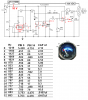
Mike, I seem to be getting stuck at the integrator and the rectifier. I'm not seeing a change of voltage as the capacitance changes. Is R 7 47K or 220K? The down load has 47 K and the thumbnail has 220K Just noticed. I add 22nf to the probe for testing and I get the frequency change but can't see the voltage change, still working on it. Will post info tomorrow.
Thanks again,
Kinarfi
 
First, I pulled the meter out and measured it, Red to Black = 305.4 Ω, Red to White(to tank wire) = 111.3Ω, Blank to White = 194.3Ω. The voltage out of the meter appears to be a voltage divider.
The attached is the schematic of what worked and after adjustments, the 2nd number by the pots is their setting.
In practice the "true opamp integrator" produced a 10 volt square wave, so I went back to an RC integrator.
Another fun little project,
Thanks for the help,
Kinarfi
 

Attachments

  • Cap Fuel Gauge Data .PNG
    Cap Fuel Gauge Data .PNG
    102.6 KB · Views: 422
  • 20101004_09.JPG
    20101004_09.JPG
    297.1 KB · Views: 184
Last edited:
Status
Not open for further replies.

Latest threads

New Articles From Microcontroller Tips

Back
Top