Continue to Site

Welcome to our site!

Electro Tech is an online community (with over 170,000 members) who enjoy talking about and building electronic circuits, projects and gadgets. To participate you need to register. Registration is free. Click here to register now.

  • Welcome to our site! Electro Tech is an online community (with over 170,000 members) who enjoy talking about and building electronic circuits, projects and gadgets. To participate you need to register. Registration is free. Click here to register now.

fuel gauge

Status
Not open for further replies.

kinarfi

Well-Known Member
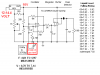
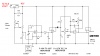
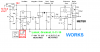
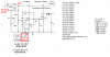
Got this capacitive fuel gauge sender design from Kit Plane and after modifications, Here's what I have. Would any one like to suggest any improvements or changes?
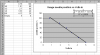
The change of voltage / level change is greater as the tank gets empty.
Jim Weir's Kitplanes Addendum see June, July, Aug 2000
Thank You,
Kinarfi
 

Attachments

  • Post.PNG
    Post.PNG
    21 KB · Views: 349
It looks like the 324 at 8.7 volts may be against it's high side rail.
 
Last edited:
It looks like the 324 at 8.7 volts may be against it's high side rail.

Sorry, forgot to mention that the op-amp is a TI TLC27M9CN, The oscillator and peak detector are working fine, but my difference amp isn't, it switches from the 0v rail the 10v rail when I lower the empty set and stays there until I remove the power and reapply.
Guess I have some more learning about difference amps to do.
kinarfi
 
You know I could be wrong but I think the + & - on the buffer amp is backwards... It's all positive feedback. Also the 8.7 volts will be above the common mode voltage (see note 5).
 
The first drawing didn't work, Maybe this one will, the difference amp & buffer - full set have been changed and tested on LT Spice. I will build and test and write down my measurements.
My variable capacitor is 2 aluminum sheets, 16" x 7" rolled up together with 1/4" bird netting between the sheets so it doesn't short out or get capillary action between the sheets. About 1 1/2" diameter.
Kinarfi
 

Attachments

  • As Built Fuel Gauge.PNG
    As Built Fuel Gauge.PNG
    17.8 KB · Views: 337
The first drawing didn't work, Maybe this one will, the difference amp & buffer - full set have been changed and tested on LT Spice. I will build and test and write down my measurements.
My variable capacitor is 2 aluminum sheets, 16" x 7" rolled up together with 1/4" bird netting between the sheets so it doesn't short out or get capillary action between the sheets. About 1 1/2" diameter.
Kinarfi


Took it to the work bench and changed a few parts and tried it with real gasoline, with proper safety precautions, and the empty set worked and the full set worked, very happy with it.
kinarfi
 

Attachments

  • As Built Fuel Gauge.PNG
    As Built Fuel Gauge.PNG
    19.2 KB · Views: 253
Took it to the work bench and changed a few parts and tried it with real gasoline, with proper safety precautions, and the empty set worked and the full set worked, very happy with it.
kinarfi

I Emailed Jim Weir, mentioned earlier, and asked his opinion of this design and his comment was "Sorry, but I just can't comment on individual designs, ESPECIALLY on potentially explosive designs. Jim"
My question is: how much of an ignition source is this design (only the variable capacitor is inside the tank) and how likely is an ignitable mixture to be inside a gas tank.
I know this is an electronics forum, but maybe some have experience in this area to share.
Thanks
Kinarfi

Well I can see Jim's point. This is one of those things people don't like to touch. You should read the story of TWA Flight 800:

The four-year NTSB investigation ended with the adoption of its final report on August 23, 2000. The report's conclusion was that the probable cause of the accident was an explosion of flammable fuel/air vapors in a fuel tank, and, although it could not be determined with certainty, the most likely cause of the explosion was a short circuit.[8] As a result of the crash, new requirements were developed for aircraft to prevent future fuel tank explosions.

Capacitive fuel probes have been used in aircraft for decades without problems. The theory behind TWA Flight 800 is that somehow a short or something caused a probe in an empty tank to ignite the fumes. The liquid isn't what gets you it is the highly explosive vapors in a partial tank.

The idea here is that you look at your circuit and your probe and figure out if something goes wrong what can happen in the tank. If I were to tell you the circuit looks fine and then something went very, very wrong and you were burned or disfigured how would I feel? The same is likely true of anyone here.

MikeMI is an aviator as well as electronic engineering type. I am sure he is familiar with capacitive probes and fuel measuring systems on aircraft. I doubt Mike would be quick to place his blessing on any circuit involving fuel for a member.

I just have reservations when it comes to things that can go bang and forum members.

Just My Take
Ron
 
I know Jim personally. He and I go way back on rec.aviation.xxx. I have attended his seminars at Oshkosh. I'm guessing that he is just being very careful...
 
Well most automotive fuel tanks have electrical fuel gauge senders in them, with open wiping contacts. A lot have electric fuel pumps in them with motor brushes, although those are inside the sealed motors so under fuel not vapour. You have got to be very unlucky to have an explosion, but it could well be fatal if you did.

If the oscillator op-amp failed on your design, there could be quite a lot of power available. It would probably need the probe to short to something as well, but that is a possible path.

You can of course insulate the probe. Also, if you were to put a large capacitor, say 1 uF, in series with the probe, that would prevent any DC current even if the probe shorted.
 
Thank you for sharing your thoughts, I did think of TWA Flight 800 and I'm certain that Jim is the type of person everyone would be proud to call "friend" and is probable being careful, may also be more correct than I would like to admit. After taking Diver300's suggestion and plugging it into spice, and looking at Jim's design in which he did that very thing, it lowers the voltage inside the tank to a 0v center sawtooth of about 2 volt p-p and a 1 Meg to ground resistor. This may be approaching an intrinsically safe design?
Again I have learned from this forum and I thank you all for your inputs and for helping to educate me.
Thank you,
Kinarfi
Here's what I have now.
 

Attachments

  • As Built Fuel Gauge.PNG
    As Built Fuel Gauge.PNG
    21.9 KB · Views: 303
Last edited:
I need a tad bit more help please, It turns out my fuel gauge works backwards or with current instead of voltage, the readings that I took are:
OCV=7.83V Needle pegged at empty.
Max current = 109ma measured with the 10 amp scale, 106.1 on the 400ma scale, needle pegged full.
Full = 98 ma @ 0.75v
3/4 = 82 ma @ 1.91v
1/2 = 71 ma @ 2.70v
1/4 = 62 ma @ 3.33v
0/4 = 52 ma @ 4.12v
empty = 39 ma @ 5.00 v (0/4 is top of the red zone, empty is bottom of red zone)

I'm looking for ways to convert what I get now (voltage 0 to 5 or 7) to what I need for the meter I have (current?) Looking at the voltage to current op-amp configuration. If you know what I need, a push in the right direction would sure be appreciated.
Kinarfi
 
I dont understand your meter. Are there three connections to it or only two? Is the case grounded? (That might be the third connection?)

The circuit should work as is with a simple voltmeter (high impedance milliAmp meter). Try connecting your DVM in volts mode where your circuit shows METER. Is the voltage there proportional to the fuel level?
 
Last edited:
Sorry for the confusion, what I have been designing is a sender unit to replace the existing unit which has 4 reed switches activated by a magnet on a float, full 3 ohms to ground and empty is 110 ohm to ground.
**broken link removed** **broken link removed**
The measurement in my previous post are what I read while watching the gauge and adjusting a pot and reading one dvm for current and another for voltage. Not the most accurate method, but the readings indicate that the gauge sends out 7.83 v and the max current is 106 ma and I calculated an internal resistance of 72 ohms. The gauge is powered by the 12.4 volts of the vehicle and sends power to the tank sender unit, pictured. I hope I explained it clearly, if not please ask.
Kinarfi
 
Last edited:
Looks like the gauge is fairly linear if you just drive it with a voltage source. Note I assumed the needle position as a percentage of travel across the face. If what I assumed is not correct, tell me...

In order to invert the gain/offset stages in Jim's circuit, I would need a plot of Voltage at the cathode of the diode vs fuel level in the circuit as it is now.
 

Attachments

  • Kguage.png
    Kguage.png
    16.4 KB · Views: 221
Last edited:
Looks like the gauge is fairly linear if you just drive it with a voltage source. Note I assumed the needle position as a percentage of travel across the face. If what I assumed is not correct, tell me...

In order to invert the gain/offset stages in Jim's circuit, I would need a plot of Voltage at the cathode of the diode vs fuel level in the circuit as it is now.

Here they are in the attachments, here's the wave form I'm getting, just FYI.
Thanks for the help,
Kinarfi
 

Attachments

  • As Built Fuel Gauge Cathode Voltage.PNG
    As Built Fuel Gauge Cathode Voltage.PNG
    21.6 KB · Views: 379
  • half.PNG
    half.PNG
    45 KB · Views: 225
I wanted you to leave a load on the Diode detector. By removing the down-stream circuit, the unloaded output across the capacitor is unrealistic. Put a 100K in parallel with the right-most 0.1uF, and plot the calibration curve again...
 

Attachments

  • As Built Fuel Gauge Cathode Voltage.PNG
    As Built Fuel Gauge Cathode Voltage.PNG
    17.7 KB · Views: 277
After a lot of work, here is my "improved" version of Jim's circuit.

1. I incorporated Jim's oscillator and other suggestions. The voltage across the sensor is constrained to be +-1V, no DC offset, shunted by a 1meg static drain resistor.

2. I made the integrator a "true opamp integrator" instead of just a simple RC network. I optimized the time constant for the range of frequency based on your measured sensor capacitance range.

3. I used an "opamp active rectifier" as a peak detector, and improved the filtering at its output.

4. I designed an inverting meter driver which is capable of sinking ~100mA to drive your weird gauge.

5. The simulation steps the sensor capacitance in seven steps from 2240pF to 25700pF (3352pF increment).

6. The plots show V(out) the voltage at the gauge input, I(R10) which is the current sourced by the gauge, and V(sen) the voltage across the sensor at eight different values of sensor capacitance. Note that there is a slight amount of compression between the C(sensor)=2240pF and C(sensor)=5592pF, but the other six steps are equally spaced.
 

Attachments

  • CapFuelGauge.png
    CapFuelGauge.png
    41.9 KB · Views: 276
  • CapFuelGaugePlots.png
    CapFuelGaugePlots.png
    82.5 KB · Views: 233
  • CapFuelGauge.asc
    4.9 KB · Views: 185
Thank you Mike, I have been out for a few days and I'm going out again shortly, so it will take a few days or weeks to sort this out, build and test, but I will certainly let you know how it worked.
Thanks Again,
Kinarfi
 
Status
Not open for further replies.

New Articles From Microcontroller Tips

Back
Top