Continue to Site

Welcome to our site!

Electro Tech is an online community (with over 170,000 members) who enjoy talking about and building electronic circuits, projects and gadgets. To participate you need to register. Registration is free. Click here to register now.

  • Welcome to our site! Electro Tech is an online community (with over 170,000 members) who enjoy talking about and building electronic circuits, projects and gadgets. To participate you need to register. Registration is free. Click here to register now.

4-Wire Strain Gauge Wiring Help

Status
Not open for further replies.

Iawia

Member
Hi All,

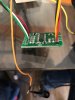
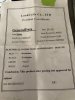
Just have a question on a S strain gauge I am trying to wire up. It has a small board attached to it (strain3.jpg). I cant find any datasheet on it, except the silly paper that came with it (strain2.jpg). The sheet says 'Excitation+-' and 'Signal+-' which are not amazing labels for electronics. I am going to assume the signal+- label is a differential which I will use to compute the load? I was going to read these using a voltmeter for testing, then use a microcontroller once I know the max voltage output.

To make things a little more confusing there is a 5th wire hanging off the cable bundle which is not connected to the little board this gauge comes with. is this the shield or to power up the gauge? I tried to apply 3.3v to the Vcc with the GND wire grounded then tried to read the differential. It reads 0.8v and when I load the gauge the value doesn't change. Slightly frustrated, I tried my luck with 5v at risk of breaking something, and still the same.

Any pointers on this I would greatly appreciate! Thanks, guys.

-t
strain 1.jpg
 

Attachments

  • strain 3.jpg
    strain 3.jpg
    436.6 KB · Views: 162
  • strain 2.jpg
    strain 2.jpg
    441.3 KB · Views: 155
The 5th wire is the shield. That should be grounded.

You wire the red wire (Excitation+) to E+ on the board, and the black wire (Excitation-) to E- on the board. Wire the green and white wires to A+ and A-

The load cell sensitivity is 2mV/V which will be at the full load of 500 kg. That means that if you use a 5 V supply, you will only get 10 mV out when the load cell has 500 kg on it. That's why you need a specialised amplifier. I would expect the green and white wires to be at nearly the same voltage at no load. The voltage on each of them would be about half the supply voltage.
 
Hi Diver,

Thank you for your response. Looking at the wiring of the board, it is how you have said. The output wires I have available are red(VCC), SCK(Y), DT(Purp), GND(Blk) at the other side of the board, plus the 5th wire which I have grounded.

Once i do this and apply 5v, it reads 71 mV between the Y/Purp and never changes. If i use 3.3v, it is 0v between them. No load or load it is the same readings.
 
How do you intend to read the HX711? It has an unusual serial communication protocol where the number of clock pulses defines the channel and gain. If you have an Arduino then there's examples available that work well.

Mike.
 
Hi Pommie, I would like to read the stain gauge with my beagle bone black which will accept analog inputs up too 1.8v. I planned on using one channel for each of the differential wires, compare them to ground then subtract the two and use a multiplier to provide the actual load. That was my plan anyway.

From examples of the HX711 in use, it appears they are using a library for the HX711 which I have found on GitHub. Transferring this library to the beagle seems quite difficult from what I am seeing involving several scripts and command prompts/file permissions sudo commands. Is there a way I can send the appropriate signals on those two wires straight away?

Thx Pommie for the information! Unfortunately, I have hit another roadblock.
 
"...I planned on using one channel for each of the differential wires..." I'd be curious how that goes, the voltages are very small and the HX711 does a good job.

What the HX711 does is provide a 24-bit ADC and a regulated voltage to the strain gauge.
The 24-bit ADC immediately following the instrumentation amplifier is key for a good signal to noise ratio.

We are currently using an HX711 on our own load cell combiner board design where i have just bit banged the code on a micro.
 
Think about the resolution you need and what the parts you have can give or work with:-

The beaglebone ADCs are 12 bit resolution.
With a direct connection, you would have to limit the load cell supply to 3.3V to keep the output (at half supply) below the 1.8V limit.

That means 500Kg = 6.6mV output.

1.8V / 4096 (2^12) means the ADC step size is about 0.44mV, giving a range of 15 counts for 0-500Kg
33Kg per ADC count.

The simplest approach for a practical minimal system may be to add a zero-offset rail to rail opamp configured as a differential amp (or a dedicated differential instrumentation amp) between the load cell and MCU ADC input.
An AD623 may be suitable:


Adding a gain stage with a gain of eg. 200 to 250, which also changes the signal to 0V referenced, would mean it can be read directly by the ADC with reasonable resolution.

250 gain would give a 0 - 1.65V range, equivalent to an ADC range of roughly 0 - 3750, so each step around 134 grams.

A dedicated load cell converter (the 24 bit one already mentioned) would still give far better results, though..
 
Just dug out some pic C code that I used to read a HX711.
Code:
#define HXCLK LATCbits.LATC2
#define HXDAT PORTCbits.RC1
#define HXCLKTRIS TRISCbits.TRISC2
#define HXDATTRIS TRISCbits.TRISC1

void initHX(){
    HXCLKTRIS=0;        //clock is output
    HXDATTRIS=1;        //data is input
    HXCLK=0;
    ANSELC=0;
}

uint8_t readyHX(){
    return(HXDAT==0);
}

uint32_t readHX(){
    uint32_t temp=0;
    if(HXDAT)           //data low if chip ready
        return(0x55);
    for(uint8_t i=0;i<24;i++){
        temp<<=1;
        HXCLK=1;
        __delay_us(1);
        if(HXDAT)
            temp++;
        HXCLK=0;
        __delay_us(1);
    }
    __delay_us(1);      //send 25 clock pulses for channel A, gain 128
    HXCLK=1;
    __delay_us(1);
    HXCLK=0;
    return temp;
}

HTH,

Mike.
 
Diver300 Thank you, today I understand what you are saying for the 10mv output.

rjenkinsgb and thank you for the breakdown of the numbers, this was very instrumental. I think i will move forward with the AD623 as it will move me forward. How to get the -5v rail, just use a inverting op amp? Also, the 'INPUT REF' should be grounded i would think? below is a graphic of my understanding of how the circuit will work, can someone confirm, i would appreciate!

450 Ohm would provide a gain of 250, so i can tune this value to calibrate the sensor. Also, i do not think i have any electrolytic caps, do you think this will be bad?

Lastly, i assume that this amp will be in the dual supply configuration? I am really a noob, thank you!

1583614039059.png


1583614293857.png
 

Attachments

  • ad623 - Operational Instrumentation Amp.pdf
    1.3 MB · Views: 151
How to get the -5v rail, just use a inverting op amp?
I think you should be able to use the "Single supply" configuration, just using +5V for the opamp and strain gauge.

The REF goes to 0V, or the ADC analog ground terminal; the output voltage is relative to that terminal.
 
Is there a reason you're not using the (HX711) board that came with the load cell? They're very accurate and easy to use.

Mike.
 
Is there a reason you're not using the (HX711) board that came with the load cell? They're very accurate and easy to use.

Mike.

From our experience they are hard to source just the chip, but for our particular project we were able to do so. They seem to be the only player in town. The KEY features that make this chip unique is the precision voltage regulation to the Sensor (which Sparkfun doesn't use correctly for a 6/7 wire strain gauge). Other KEY features include the onboard instrumentation amplifier followed by a 24-Bit ADC.... You could probably get away with another IC that just has the Instrumentation amplifier ADC combination, but probably not the precision regulator built in. Oh and it also has a 50/60Hz filter built in. So there are a couple of things going for that IC other than it's availability.

Note: To utilize the Voltage regulation correctly, the +Sense line needs to tie into the FeedBack circuit as a return path from the sensor. As it is the Feedback circuit goes directly to the Collector of the external PNP transistor. The GND and AGND is ok and the -Sense can be used as feedback to monitor if the strain gauge is attached at the sight. i.e. anti theft, cutting of the line, etc.
 
Last edited:
In the top post the OP mentions (and inluded a photo of) a board which came with the load cell. I'm pretty sure that board contains a HX711.

Mike.
 
It does, but our client is not interested in the breakout board (we have that board as well) .... in this case we are designing our own board that functions as a load cell combiner with the HX711 chip on the board itself.

Attached is a completed board... The HX711 is on the front of the board on the image
 

Attachments

  • 224c7ab1-02fe-4585-bd1e-3e17711da43f.jpg
    224c7ab1-02fe-4585-bd1e-3e17711da43f.jpg
    222.5 KB · Views: 166
I found the cheap HX boards work well. I think the OP will get more (quicker) success using it.

Mike.
 
Hi Pommie, I have opted not to use the HX711 due to the fact that I need to change from the beagle bone black (bbb) 1 Ghz ARM processor to an Arduino Uno 20 MHz. Uno has a windows type file system which is very easy to use, and hence easy to place the associated C libraries. I fear that if I change platforms just more problems will crop up, including burn out. I am an ME so I don't completely understand the ee world but am getting on.

Secondly, using the bbb file system with HX711 is possible, but from my research it requires a load of super cryptic Linux cs commands like 'sudo' and also changing file write permissions. The learning curve is approaching infinity! (yes, I know, I should make more talented friends)
 
Why would you need to change the board? The HX711 will work with any board. I've used them with many different chips from a lowly 8 pin pic to an ESP8266. Just bitbang the code as shown above. Note, a 5kg load cell with a HX starts with a negative value and goes positive when loaded.

Whichever way you get the value, you'll still need to have a zero offset and scale value.

Mike.
 
Some observations ... The HX711 boards seem to be happy at around 4V ... We have noticed some erratic behavior when the supply voltage is at 5V or 5.5V maximum as indicated in the datasheet.

Here is some PIC Assembly code targeted for a PIC16F15323 . It is intended to be included during the initialization section prior to the "main loop".
i.e. #include "HX711 Subroutines.inc"

It is then executed with a "call Read_HX711" within the main loop of the program ... the result is returned in variables "HX711_U" , "HX711_H", and "HX711" ... If the HX711 is not ready, the routine will fall through and return from the call without updating the variables or waiting for the HX711 to become ready. Simply call the routine again the next time around.


Code:
;*******************************************************************************


; HX711_Subroutines


;*******************************************************************************


    #define    HX711_DAT   PORTC,1             ;Define RC0 as DATA input
    #define    HX711_CLK   LATC,0              ;Define RC1 as CLOCK output

HX711               equ        d'110'          ;Allocate Variables
HX711_H             equ        d'111'
HX711_U             equ        d'112'
HX711_BIT_Counter   equ        d'113'

    banksel    ANSELC
    bcf        ANSELC    ,0                    ;Disable analog mode on RC0  
    bcf        ANSELC    ,1                    ;Disable analog mode on RC1

    banksel    LATC
    bcf        LATC    ,0                      ;Preset OUTPUT PIN to LOW

    banksel    TRISC
    bcf        TRISC    ,0                     ;DEFINE RC0 as OUTPUT

    goto       HX711_Subroutines_Done          ;Jump to END of HX711 Subroutines

;---------------------------------------------------------
;---------------------------------------------------------

Read_HX711:
    banksel    PORTC
    btfsc      HX711_DAT                       ;Check if HX711 is ready
    goto       HX711_NOT_Ready

    banksel    HX711                           ;Set BIT Counter
    movlw      #8
    movwf      HX711_BIT_Counter

HX711_ShiftOut_H:
    banksel    PORTC                           ;Clock
    bsf        HX711_CLK
    nop
    bcf        HX711_CLK
    movf       PORTC    ,W                     ;Read Data BIT
    rrf        WREG
    rrf        WREG
    banksel    HX711
    rlf        HX711_U
    decfsz     HX711_BIT_Counter               ;Done with HIGH BYTE?
    goto       HX711_ShiftOut_H
    movlw      #8                              ;Set BIT Counter
    movwf      HX711_BIT_Counter

HX711_ShiftOut_M:
    banksel    PORTC                           ;Clock
    bsf        HX711_CLK
    nop
    bcf        HX711_CLK      
    movf       PORTC    ,W                     ;Read Data BIT
    rrf        WREG
    rrf        WREG
    banksel    HX711_H          
    rlf        HX711_H
    decfsz     HX711_BIT_Counter               ;Done with MIDDLE BYTE?
    goto       HX711_ShiftOut_M
    movlw      #8                              ;Set BIT Counter
    movwf      HX711_BIT_Counter

HX711_ShiftOut_L:
    banksel    PORTC                           ;Clock
    bsf        HX711_CLK
    nop
    bcf        HX711_CLK
    movf       PORTC    ,W                     ;Read Data BIT
    rrf        WREG
    rrf        WREG
    banksel    HX711
    rlf        HX711
    decfsz     HX711_BIT_Counter               ;Done with LOW BYTE?
    goto       HX711_ShiftOut_L

Define_Resolution:
    banksel    PORTC
    bsf        HX711_CLK                       ;send 25 clock pulses for channel A, gain 128
    nop
    bcf        HX711_CLK

HX711_NOT_Ready:
HX711_Subroutines_Done:

     return
 
Last edited:
Status
Not open for further replies.

Latest threads

Back
Top