Continue to Site

Welcome to our site!

Electro Tech is an online community (with over 170,000 members) who enjoy talking about and building electronic circuits, projects and gadgets. To participate you need to register. Registration is free. Click here to register now.

  • Welcome to our site! Electro Tech is an online community (with over 170,000 members) who enjoy talking about and building electronic circuits, projects and gadgets. To participate you need to register. Registration is free. Click here to register now.

fuel gauge project

Status
Not open for further replies.

scopeman

New Member
Hi All.. Scratching my head here! does anyone have a circuit solution to a project I am working on?

I have a WWII Fuel gauge out of a B-17 Bomber that will work on 12v DC, if I put 128K ohms inline the gauge reads "full" my Jeeps fuel tank is 17 ohms full and 80 ohms empty. trying to create a circuit that will tie the meter into the tank sensor and read "E" when the tank is empty and "F" when its full! any ideas?

Thanks,
Kendall ☺

So your end goal here is you want to use the aircraft fuel gauge in your jeep? Am I understanding this right?

You stated that you measured the resistance from the fuel sensor in your jeep to be 17Ω for a full tank and 80Ω for an empty tank. Were these resistances you measured between the fuel sensor output and ground or between the fuel sensor output and +12V? A more useful thing to measure would be the voltage between the sensor output and ground. Once you know that you'll know the range of voltage that the sensor outputs to indicate full, empty, and anywhere in between. We already know that it's going to be somewhere between 0 and 13.6V but exactly where, I don't know.

You also stated that when you hook up the aircraft fuel gauge to a 12V source and place a 128KΩ resistor in series with the input, the gauge reads full. What resistance can you replace the 128KΩ with to make the gauge read empty?

You are going to have to play around with it a little to get some more information before you can complete the project.
 
Thanks Vne147,

Yes I'm replacing all my gauges with such! my original fuel gauge has never worked, I used a ohm meter to read the tank! 17Ω full about 80Ω empty. got a great fuel gauge from a WWII warplane the reads 128K ohms full and 0Ω empty. I'm not sure of the voltage thru the fuel tank is, just read the across the 12v and wire to the tank sensor with my meter.

Right now I'm looking at a inverting op amp configuration using the sensor as a input resistor having a 100kΩ as a feedback resistor that sets what voltage is needed on the output to counteract the input current to make the - input of the op amp balance the reference on the + input of the op amp.
 
You description is somewhat confusing. What resistance does the warplane "read"? What power does it require? Also don't understand what you are trying to do with the op amp.

A wiring diagram would be helpful.
 
Last edited:
Below is a diagram with the op amp configuration.

**broken link removed**

the output indicator is electromagnetic, 0 ohms empty and 128k ohms full
 
That's where I'm confused. You are trying to apply a voltage to the fuel gauge but you say it responds to resistance. Is that the resistance of a resistor in series when the gauge is connected to 12V? You don't show how the fuel gauge is connected in your schematic.

Edit: What is the current through the gauge when at zero ohms?
 
Last edited:
Carl I'm not sure what the current is thru the new gage, it would be connected just like the old fuel gauge thinking it is reading a resistance. I have full control with the new meter across 12V empty to full 0-128K ohms. the circuit is you show the use of the TL082
 
You need to know the meter current to determine if the op amp can drive the meter. Just use a multimeter to measure the current with zero ohms in the meter circuit.

The TL082 will not work well in this application. For a single supply you need a rail-to-rail type op amp.
 
Hello crutschow, at 12.44v DC I have a reading of 0.14A with no resistance. the meter of course pegs out.

If the current through the fuel gauge with 12.44 V applied and 0Ω in series is 140 mA, that mean that the fuel gauge has a resistance equavalent to approximately 90Ω. It takes 128KΩ to make the gauge read full which is several orders of magnitude higher than 90Ω. That's kind of suprising to me but I'm no expert.

I think it is important to know the method by which you determined the 128KΩ resistance value is what is necessary to make the guage indicate full. Did you just happen to have a 128KΩ resistor lying around and tried it out or did you use a potentiometer and dialed it up until the guage read full? If you just used a single resistor, it is possible that the 128KΩ value simply "pegged out" your gauge and in reality, the resistance necessary to make the gauge read full could be much less.

Also, did you put the 128 KΩ in between the 12.44V and the gauge or in between the guage and ground?
 
The way I had originally come up with the 128KΩ was physically adding resistors in series with the 12v and added them all up once I had a 'full" reading. which came to 128KΩ
and yes I place said resistors thru the (+) and grounded the(C) terminal and got a "full" reading.
 
Someone had sent me this as an option!!

Hello,

You could do this with a very cheap microcontroller and a digital potentiometer.

A simple circuit could measure the output of the potential divider made with the Jeep fuel tank sensor and R1 (in the diagram).

The microcontroller could then calculate the resistance and output the appropriate resistance via the digital potentiometer which will be presented to the B17 gauge.

diagram below:

Physics Forums

This is very doable and would probably be the most accurate way but there are ways of doing it with an analog circuit. Are you familiar with PICs? You can use the onboard ADC to measure the resistance of your car's fuel gauge and then send an output (via, I2C or some other protocol) to a digital potentiometer.

Silly question. Does the gauge read empty or full when no power is applied?

BTW, your link to the physic forum requires a login so I didn't see what was there.
 
Hello crutschow, at 12.44v DC I have a reading of 0.14A with no resistance. the meter of course pegs out.
It's pegging at the empty position?

If so what is the current when it just reads empty but not pegged?
 
no I am not familiar with PICs.. just looking for a economical solution that will be pretty accurate. The gauge reads empty with no power applied.
**broken link removed**
 
The PIC idea is pretty simple but not if you've never played with PICs before. You would need to write the program which wouldn't be too complicated but once again if you've never played with PICs before, it would be a challenge. You would then need to get the program you wrote onto the PIC which would require a piece of hardware called a programmer. They are inexpensive and you could probably get one for around $20.

The PIC option aside, I have to say that I'm slightly confused by the information you've given so far. I'm not saying it's innacurate, it's just not what I would have expected. I'm not an expert and don't know about the inner workings of the fuel gauge. So far what you've figured out is:

  1. When the gauge is unpowered (i.e. see 0 V) it indicates empty.
  2. When you apply 12V and place no resistor, it indicates empty.
  3. When you apply 12V and place a 128 KΩ resistor in series with the gauge, it indicates full.
  4. With no resesitor, the current through the gauge is 140 mA.

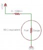
First off, I'm assuming the setup you're using to test the gauge is something like the diagram I've attached to this post.

As you vary the external resistance (labeled 0 - 128KΩ), the voltage measured across the gauge and also the current through the circuit changes. When the external resistance is 0, the voltage across the gauge is 12V and the current is greatest. When the external resistance is 128 KΩ, the voltage across the gauge is approximately zero and the current is the least.

From what you said, when the external resistance is 128KΩ (i.e. 0V across the gauge and lowest current) it indicates full. But then when the gauge is unpowered (also 0V across the gauge and 0 current) it indicates empty. This seems inconsistent and counter-intuitive to me at least.

Another thing about this that seems strange to me is the fact that you have to use such a large external resistance to change what the gauge reads.

From item 4 we can figure out that the equivalent resistance of the gauge is 90 Ω because:

V = IR so R = V/I = 12.44/.14 ≈ 90Ω

We can see that the equivalent resistance of the gauge is several orders of magnitude less than the 128 KΩ resistor. If the range of external resistance you need to make the guage work is 0 - 128 KΩ then the voltage across the gauge drops very close to zero when you've used only about 10% of the 0 - 128KΩ range. Once again, I'm no expert but that just doesn't seem right.

It is hard to troubleshoot this thing and figure it out through forum posts. I would likely have a lot more luck if I physically had the gauge to play with. If I were doing this project I would next try the following steps:

If you have a variable power supply, do not put any external resistors in series with the gauge and hook up the power supply to it. Then vary the volatge applied to the gauge between 0 - 12V making notes of which voltages caused the gauge to indicate full, empty, half, 3/4, etc.

If you don't have a vriable power supply, hook up the gauage to the 12V source and vary the external resistance. I would like to know what resistance causes the gauge to read empty, full, half 3/4 etc. Make sure that when you measure for empty and full that the gauge is not pegged out at full or empty. The current at each point might also be helpful information. Hope this helps.
 

Attachments

  • fuel gauge.JPG
    fuel gauge.JPG
    17.1 KB · Views: 865
Last edited:
Now that I realize what you meant by zero resistance (an open or no resistance, not a short) then I understand what the gauge is doing.

But as vne147 stated, to really design a proper interface circuit, the actual current of the gauge at various indications (particularly empty and full) needs to be known. (The minimum current that just indicates empty is required, not zero current.)
 
Status
Not open for further replies.

Latest threads

New Articles From Microcontroller Tips

Back
Top