Continue to Site

Welcome to our site!

Electro Tech is an online community (with over 170,000 members) who enjoy talking about and building electronic circuits, projects and gadgets. To participate you need to register. Registration is free. Click here to register now.

  • Welcome to our site! Electro Tech is an online community (with over 170,000 members) who enjoy talking about and building electronic circuits, projects and gadgets. To participate you need to register. Registration is free. Click here to register now.

fuel gauge project

Status
Not open for further replies.
(an open or no resistance, not a short)

I don't think I understand. An open circuit has effectively infinite resistance. He must have shorted it by placing 12V directly to the (+) terminal and grounding the (C) terminal. This is how I interpreted what he stated at 0 resistance. It could not have been open otherwise how would have have measured 140 mA of current?
 
Scopeman has not gathered enough info to design a suitable circuit.

It is unlikely that even if you match the sender and the gauge at the two endpoints (i.e. Empty and Full), that the resulting gauge indication would be linear (or very accurate).

Lack of linearity is mostly caused by:

Mechanical stops on the sender float arm (to keep the float from rubbing on the top or bottom of the tank).

The geometry of the float arm as it causes the wiper to traverse the rehostat.

The linearity of the rehostat progressive winding.

The non-linearity caused by putting a fixed resistor in series with the sender in order to create a voltage divider to produce a voltage proportional to wiper position.

Without testing it, there is no basis to know if the gauge reading is proportional to input voltage, input current, or the resistance tied between the input to ground, or input to + supply?

You need to plot the voltage out of the sender (configured into a voltage divider) as you add a gallon at a time to the fuel tank.

You need to plot the needle position on the gauge vs voltage in/current in/resistance into the gauge.

Both tests need to done at a known supply voltage. If you want accuracy, you might have to regulate the sender excitation voltage and the gauge voltage...
 
Some thoughts, but not a direct solution: First off, automotive guages USUALLY are current operated, hence the low resistance of the sending unit. Not so in recent models with computers, but almost always in older vehicles. They also usually have a primitive voltage regulator to insulate instrument power from battery condition. (10v or 5v)

Aircraft instruments are a whole 'nuther ball game. A good many are voltage sensitive, probably the warbird instruments are as well.

What you will need to do is:
1) Determine what voltage is necessary to drive the meter from 1% to full scale. (Don't measure from zero, get the needle a hair off the peg) You may need to go upwards of 24 volts to get full scale.
2) Provide a load resistor, probably a fairly low value, with good wattage, to get a linear reading from the tank sending unit. Needn't be a particular value, just reasonably linear.
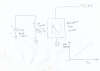
3) Use an OP-Amp to scale and offset your derived voltage values as needed. Then a driver transistor to carry the current of the meter.

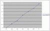
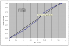
NAPA carries replacement tank sending units, you may find it to your advantage to get one with a more usable range. Also, keep in mind, the end result will NOT be linear. The float moves through an arc and is more sensitive near the center, becoming less so as you approach the limits.

Similar circuit was used to install a 3914 bar-graph meter in a '49 Chev 1 ton flatbed a few(23) years back. The 6 volt instruments were running from a 12 volt battery and near useless. The bar graphs were behind smoked plexiglas and invisible until the switch was on.
 
Thanks Guys..
Attached is a pic of the 15 gal. sending for a 77' CJ7 Jeep I have one that I pulled out of the old tank when I replaced that tank. (if I need to break it down to see what type of system it has I can do that) but it sounds like I need to start at 0 gallons and add fuel to chart out the voltage. if I'm understanding you correctly.

**broken link removed**
 
I also took the 12.44v battery and connected the gauge to ground and (+) and connected various resistors to achieve 1%, 1/8 tank, 1/4 tank, 1/2 tank and 3/4 tank there about on the gauge:

1% over Empty=278kΩ

1/8 tank= 63kΩ

1/4 tank= 79kΩ

1/2 tank= 4.8kΩ

3/4 tank= 109kΩ

and of course Full tank= 128KΩ

I don't know why the tank reading reads like that!
but I metered each resistor out and added them up.
That makes no sense. How can 4.8kΩ give a 1/2 tank reading when 1/4 tank and 3/4 tank take a much higher resistance.

Where did you connect the resistance? Post a schematic.
 
Last edited:
Are you sure you are correctly interpreting the color bands on the resistors? Have you checked the resistors with a multimeter to verify they are correct?
 
Except for the ~empty and 1/2 full, the resistance settings are very linear (in Excel).

Ken
 
Linearity or non-linearity aside, I don't understand why the quantity goes up as resistance is increased. The higher resistance there is, the less current flows through the gauge and the closer it approximates the unpowered state. Why would an unpowered gauge (i.e. zero current) indicate empty while a powered gauge with the least amount of current flowing through it (i.e. the highest resistance) indicate full. It seems very inconsistent. If he was hooking up the resistors in parallel to the two terminals (between + and C) on the gauge this would make sense but he says it's a series connection. I hope we figure this out because it's bugging me.
 
If the resistances that Scopeman reported are correct, then the gauge is expecting a voltage input (not a varying resistance to ground). That was the open question, and so now I would like Scopeman to connect a 1000Ω pot (wiper to the gauge input, top end to 12.4V, bottom end to 0V) and plot gauge reading vs voltage at the pot wiper. Start with the wiper at the ground end, and ramp it up slowly, record the gauge input voltage corresponding to E, 1/8, 1/4, etc.

For the sender, I recommend making a voltage divider consisting of a fixed 1% resistor (say a 1000Ω) connected between 12.4V and sender terminal. Connect the sender ground to 0V. Record the voltage at the sender terminal vs number of gallons added to the tank. This will give a plot of voltage from the sender and let us assess the linearity.

With a plot of gauge reading vs voltage in, we can implement the required gain and offset to fit the end points. If the linearity is too far off, we can add a diode network around the opamp to "bend" the transfer function to get at least a three point fit (middle and both ends).
 
Last edited:
Hello Mike,
I drained the tank and drew up this schematic. is this the test point (TP) to obtain said voltages? don't want to blow myself up on what fumes are in the tank!! He He..

Thanks..
Kendall

**broken link removed**
 
Yes, that is the test configuration.

Question about the VOM? How accurate? Meter type or digital? I would expect that you could use like 5VDC full-scale for your tests.

What is the source of the 12.4V? Is that the Jeep's battery?

Do you have an adjustable, regulated power supply? If so, set it for 10.0V and use it to power the 1K resistor for your gallon-at-a-time filling test rather than the battery. I'm trying to anticipate what voltage variation will come out of the sender as the battery voltage varies from ~12.5V with engine stopped vs ~14.4V with engine running.
 
Thanks Mike, I have 2 digital meters, should be fine. may drop the tank to make sure the float is no sticking! plus I can beanch test. Iam using a stand alone car battery, I have a 10A varaible supply if this would be better.

Kendall
 
Do the fill test with a 10V reference. That will eliminate the effect of the battery voltage variation.

It may not have been clear several posts ago, but in addition to the fill test, I want you to do a separate test, as shown below:
 

Attachments

  • MeterTest.png
    MeterTest.png
    348.1 KB · Views: 354
Hello Mike, did some test with the meter!

using 10v thru a 10k ohm pot I have voltages at locations needed:

E=ov
1/8 = .6 v
1/4 = 1.09 v
1/2 = 1.94 v
3/4 = 2.5 v
7/8 = 3 v
F = 3.72 v

been very cold here want to drop the tank and replace the sending unit with a new one I had and start adding the fuel!
now I don't know how accurate the power supply is and the digital meter but I will make the test with my other meter as well.
 
Looks good in Excel.

Ken
 

Attachments

  • Fuel gauge.gif
    Fuel gauge.gif
    3.6 KB · Views: 298
Looks good, but get the voltage for 3/8 and 5/8. Here is a straight line fit.

Be sure to use the same voltmeter when you do fill-tank-a-gallon-at-a-time test
 

Attachments

  • Gauge.png
    Gauge.png
    13.4 KB · Views: 309
Last edited:
got a question, do I divide the 1/8, 1/4 and so on spaces on the gauge between the E and F or divide this between 0 and 430 gals? the reason I ask is the range is not consistent from E- F!!

**broken link removed**

Thanks..
 
Status
Not open for further replies.

Latest threads

New Articles From Microcontroller Tips

Back
Top