Continue to Site

Welcome to our site!

Electro Tech is an online community (with over 170,000 members) who enjoy talking about and building electronic circuits, projects and gadgets. To participate you need to register. Registration is free. Click here to register now.

  • Welcome to our site! Electro Tech is an online community (with over 170,000 members) who enjoy talking about and building electronic circuits, projects and gadgets. To participate you need to register. Registration is free. Click here to register now.

fuel gauge project

Status
Not open for further replies.
If I divide all the fractions between E & F i come up with:

E = 0 v
1/8 = .434 v
1/4 = .848 v
3/8 = 1.34 v
1/2 = 1.90 v
5/8 = 2.36 v
3/4 = 2.84 v
7/8 = 3.24 v
F = 3.72 v
 
Oh, I thought it was marked in 1/8ths, but obviously not. As non-linear as the scale is, it looks like they were trying to linearize a tank that had non-vertical sides. As non-linear as the markings are, it will be difficult to match it to your sender; however, we can certainly match it at E and F.

Repeat the gauge reading (0 to 430) vs volts-in at each 50 gals.

btw- what aircraft was the gauge out of? If it was a military aircraft, the guage probably originally was powered by 28V. I wonder what it does as the supply voltage is lowered from 28V down to 14V where you will be running it?
 
This looks better:
 

Attachments

  • Gauge.png
    Gauge.png
    18.9 KB · Views: 322
Looks like a good job for a PIC with a look-up table if you want to keep the Meters markings proportional to the tanks fuel volume.

Ken
 
Hi Guys,
Thanks.. I think this came of a B-17 or B29 that very well have been a 28v system!! With the CJ7 Jeep's Chevy 350 sucking the fuel, Just need to be able to know when I'm full/empty/half way. want be reading the gauge numbers other than knowing the fuel consumption from needle moment. . I can do the 50 gal test and see how this pans out.

Kendall
 
Here is the voltages I came up with:

Gallons Volts

50 .545
100 1.046
150 1.516
200 1.816
250 2.132
300 2.352
350 2.719
400 3.291
410 3.433
420 3.565
430 3.740
 
Not too linear...but not too bad. Makes you wonder how linear/accurate the Jeep's original fuel gauge/sender was? At least in a Jeep you can pull over to the side of the trail...not too easy in a B-17. ;)

Ken
 

Attachments

  • NEW-1.jpg
    NEW-1.jpg
    21.2 KB · Views: 290
Last edited:
When I joined this thread, I mentioned that I had some experience with float-based fuel quantity indicators. In case you are interested, you can read something I previously wrote and posted in another forum...
 

Attachments

  • FuelSender.txt
    3.7 KB · Views: 312
  • BEND.TXT
    3.2 KB · Views: 321
  • Fuel.png
    Fuel.png
    33.2 KB · Views: 310
Very nice work Mike!!
that's one of the reasons I never replace the sender on the new tank I installed, the float on the old tank seem to fit fine and the new sender I have didn't fit unless you bent the float arm up away from the bottom of the tank! I thought it may change everything in the gauge system. (with the original fuel gauge)
I am planning to use the new sender and make the adjustments needed to measure as close as I can to the bottom of the tank.

Kendall
 
Hi guys,

I have topped off the tank!!

with a 10v input thru a 1126 Ω resistor I have obtained voltages listed herein:

There is about 1.25 Gallons in the tank before I start!
that my reserve margin!!

Added Gallons Volts

1 .529 v
2 .497 v
3 .375 v
4 .309 v
5 .271 v
6 .236 v
7 .216 v
8 .189 v
9 .185 v
10 .162 v
11 .150 v
12 .135 v
13 .126 v
3/4 gallon (top off) .126 v
 
Not so very linear. :(

Ken
 

Attachments

  • FUELSEND.jpg
    FUELSEND.jpg
    20.9 KB · Views: 330
I have topped off the tank!!

with a 10v input thru a 1126 Ω resistor I have obtained voltages listed herein:
...

Hi

OK, I have a design which linearizes the sender curve and fits the meter at two points. I need one more piece of info:

If you operate the meter (gauge) off a power supply adjusted to 12.00V, how much current does it draw?

I need this to finalize the voltage regulator. The opamp circuit depends on the reference voltage.
 
Last edited:
The Design

Here is my solution to Scopeman's Jeep Fuel Gauge question. I present it here to show the technique of using EXCEL for modeling the fuel tank sender, and using LTSpice to test a proposed circuit to drive the gauge from the sender.

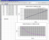
Look at the EXCEL Spread sheet.
excel-png.36742


Column A is the voltage across the Sender with the Sender connected to an 1126 Ohm resistor fed from a 10.0V DC power supply. Scopeman posted the voltage out of this circuit as fuel was added one gallon at a time. The Row number in the spread sheet is gallons added, 1 - 13. As was pointed out, the voltage vs gallons plot is quite non-linear, and is not useful for driving the Fuel Gauge directly.

I know from previous experience that most automotive fuel gauges are just a DC milli-amp meter wired in series with the fuel tank sender. Such a fuel gauge is usually fed from a regulated DC voltage derived from the car's battery voltage. This suggests that the current through the sender and meter is proportional to the float position, so I set about to determine the sensor current vs gallons added from Scopeman's posted data.

First, I used the spreadsheet to calculate the Sender resistance (Rs) vs gallons. The Rs is calculated this way:

Vs = 10.0*(Rs/(1126+Rs)) [the familiar voltage divider equation]

Rearranging:
1126*Vs + Vs*Rs = 10*Rs
1126*Vs = Rs(10 - Vs)
Rs = 1126*Vs/(10-Vs)

Col. B is Rs calculated from each measured Vs (col A).

Next, I wanted to know what the current through Rs would be if it were fed from a constant voltage. Wanting to keep the current through the sender to a low value, like less than 10mA, I choose 0.1V as the applied voltage. In col C. I calculate the current through Rs with 0.1V applied across Rs, so Is = E/Rs = 0.1/colB.

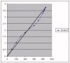
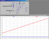
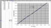
Next, I plotted the calculated sender current Is vs gallons, and as I expected, the data points are quite linear. I used the TRENDLINE feature in EXCEL (least square error regression) to fit a y=mx+b straight line through those points. This is shown as the black line in the plot. Also shown are the m and b coefficients of the fitted line as reported by EXCEL.

I then created col. E which is the linearized calculated current LIs through the sender based on the y=mx + b line as determined above. Finally, the linearized sender resistance is LRs = E/I = 0.1/LRs. The final equation simplifies to:

LRs=100/(gal*0.4516+0.9337)

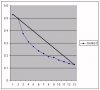
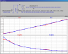
The calculated sensor resistance (blue trace) and the linearized sensor resistance (purple trace) are superimposed on the plot.

Since I want to simulate Scopeman's circuit in LTSpice, I need a parameterized model of Rs vs gallons that I can use in the schematic. To validate the model derived above, I created this simple circuit (SenderI.asc) to simulate and compare the derived model for the sender to the calculated sender resistances derived from measurements.

senderi-png.36743


For you LTSpice fans, note the use of the parameter "gal" to sweep the two versions of Rs. No surprise that these look just like the EXCEL plots.

So, if the current through the sensor is proportional to gallons in the tank, how do you make a circuit which makes a voltage proportional to the current, which is what we need to drive Scopeman's B17 fuel gauge?

He previously posted data which shows that the gauge reading is more-or-less proportional to the voltage input to the gauge. If we can make the gauge input 3.74V it will display full (430gal).

senderv-png.36744


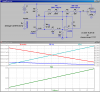
SenderV.asc is a simplified schematic of an op-amp current-to-voltage converter which does this. A fixed bias voltage of 0.1V is applied to the non-inverting input of the op-amp. Because the op-amp drives its output so as to make the voltage difference between the non-inverting input and the inverting input close to zero, this applies the assumed 0.1V to the sender, too. The sender current (created by the 0.1V across it) also flows in R2, making

Vout = 0.1 + R2*Is.

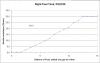
Look at the plot. Note that with R2 = 650 Ohm, V(out) is almost ready to apply to the gauge. Note that the R2 determines the slope, so we can tweak R2 to fit the full end of the range. However, there is an offset that must be dealt with.

Because of the way I modeled Rs, Is can never go to zero, so the offset is slightly more than the 0.1V implied by the equation above.

The solution to the zero offset is to inject a small current into the inverting input, adjusted to get the desired gauge reading at 1 gallon, and then tweak R2 a bit more to get the 3.74V into the gauge when tank is full.

gaugedriver-png.36745


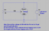
The circuit depends on having a fixed voltage of 0.1V across the sender, and having a a fixed offset current into the inverting input on the op-amp. To create these from the Jeep's Battery, which will vary from ~12V to 14.5V depending on how fast the engine is running, I include a LM431 shunt-regulator.

Two trim-pots set the 1 gallon and 13 gallon indication on the meter, respectively. First, preset both pots to the middle of their range. Substitute a 70 Ohm resistor for Rs, and set the ZERO pot to get a 50 gal reading on the gauge. Then substitute a 15 Ohm resistor for Rs and adjust the GAIN pot to get 430 gal on the gauge. The adjustments will interact a bit, so go back and forth between the two resistors/adjustments a couple of times. You are effectively fitting the circuit output to the gauge at two points, full and nearly empty.

Note, as shown, the gauge is being operated directly off the battery voltage. If normal battery voltage fluctuations cause a problem, then I have a design for an ultra-low drop-out voltage regulator to run it off a fixed 12.0V. Scopeman, You will have to determine if that is necessary.
 

Attachments

  • ExCel.png
    ExCel.png
    61.4 KB · Views: 975
  • SenderI.png
    SenderI.png
    41.4 KB · Views: 926
  • SenderV.png
    SenderV.png
    28.5 KB · Views: 961
  • GaugeDriver.png
    GaugeDriver.png
    50.2 KB · Views: 915
Last edited:
Hi Mike,

Thanks for the input!! I hope you had a good holiday.
been crazy here!!, I will go over all this soon.. but a quick question:
on the final schematic the gauge shows a gnd., + and input. the only terminals on the rear of this gauge is a (+) and (C)

just an FYI..

Have a great New Years!!


Kendall
 
... but a quick question:
on the final schematic the gauge shows a gnd., + and input. the only terminals on the rear of this gauge is a (+) and (C)

Kendall

When you did the gauge test, where did you connect the supply?
+ and the can, with the pot wiper to C?
 
Now I'm totally confused. I am under the impression that your gauge and similar automotive gauges have three terminals:

V+ (supply) which in the original application would have been connected to 28V, but for your application would be connected to the 12 to 14.5V electrical system in your Jeep. For the linearity test, I wanted you to power it with a ~12V supply or battery.

Gnd, which is likely the gauge case. In the B17, the case is grounded to the airframe, and that is the return path to to the 28V DC supply, and is also the return path for Vin, described below.

Vin, which normally is wired to the sender in the fuel tank. Vin has a variable voltage on it with respect to GND.

I'm assuming that the gauge is a three terminal device, with one of the terminals being the case. If you only had two connections to it during testing, I cant figure out how you had it connected?

Still open is the question of what the gauge does when the input voltage goes from 12.0 (low battery) to 14.5V (alternator charging, full battery)? How does that effect the gauge reading with a given, fixed input to Vin, say 3.00V?

Here is the test again:
 

Attachments

  • GaugeTest.P.png
    GaugeTest.P.png
    23.7 KB · Views: 303
Last edited:
Now I'm totally confused. I am under the impression that your gauge and similar automotive gauges have three terminals

I was confused too. That's what I was trying to get clarification on when I posted the simplified schematic way back on ye old page 2 of this thread.
 
Hello Guys, Sorry for any mix-up; when I started the Thread on page one #13 I was trying to describe my test connections. If need I can start over on all test! or can we work with what we have so far? I metered across 0 and + and got .82K ohms nothing to ground.

Kendall

**broken link removed**[/IMG]
 
Status
Not open for further replies.

Latest threads

New Articles From Microcontroller Tips

Back
Top