Continue to Site

Welcome to our site!

Electro Tech is an online community (with over 170,000 members) who enjoy talking about and building electronic circuits, projects and gadgets. To participate you need to register. Registration is free. Click here to register now.

  • Welcome to our site! Electro Tech is an online community (with over 170,000 members) who enjoy talking about and building electronic circuits, projects and gadgets. To participate you need to register. Registration is free. Click here to register now.

Frequency

Status
Not open for further replies.

BCHurricane89

New Member
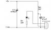
Hello, I just built this little device: **broken link removed**

but on the schematic, it shows the variable resistor connected. The problem is, there is 2 wires, but 3 leads on the variable resistor. I used a multimeter, and found 2 pins to connect it to, where I get anywhere from 0 -10K like it should. Do I still need to connect to the 3rd lead to make it work properly? I see it does show another wire in the schematic.


Also, I plugged everything in, and tested with camera. Infrared light is emitting from the device, so I know it works. Yet I cant get it to block TV signals. is there a device I can build, or a way to see what frequency is being emitted from my device? Maybe a multimeter or something, because I heard TV usually emit about 38Hz or something?
 
You don't need to connect the third pin of the pot, but you do need to adjust the pot to give the required 38KHz output.

However, it's output is so puny it's not going to jam very much at all.
 
Instructables are designed by guys who know nothing about electronics.
The current in the two diodes is higher than the small amount of current in the IR LEDs.
The circuit needs a supply bypass capacitor.

If the leads on the transistor, diodes or IR LEDs are backwards then the circuit won't work.
 
ahh I see audioguru, you made this here:
remote-jammer-png.17695

which should mean if I rearrange the parts a little, to this schematic, I should get the signal jammer to work.

Antoher quick question, does it matter what watt the resistors are?, like all the ones im using are 1/2 watt, except the 1K ohm resistor, which is 1/4 watt. are these watts fine?
 
but on the schematic, it shows the variable resistor connected. The problem is, there is 2 wires, but 3 leads on the variable resistor. I used a multimeter, and found 2 pins to connect it to, where I get anywhere from 0 -10K like it should. Do I still need to connect to the 3rd lead to make it work properly? I see it does show another wire in the schematic.
The only reason to connect the 3rd lead is to prevent a momentary open circuit when adjusting the pot (if the wiper momentarily loses contact). For your circuit that is not a problem.
 
If you don't have a frequency counter or oscilloscope, it'll be tough to find 38 khz. A cheap and simple way might be to find or by an IR receiver module (about $1.00, free from an old TV or VCR, anything with an IR remote). Nigel's tutorials have a good hook up diagram, only a couple of small caps and a resistor. You don't need a PIC (who does :) ), just use an LED on the output. They are active Low, witch means the LED will be on, until it receives a signal. Your TV remote should make it blink, when you adjust the pot the LED will go out when you find the right frequency...

Nigel's tutorials are great, I've used some of his stuff with AVR, and help a lot. I did something similar, but just to test the IR receiver module, have both a counter and scope...
 
Last edited:
would you have a link to one of his tutorials? im looking on this site, but cannot find much.


You don't need the whole circuit, just the receiver portion on the right.

*Edit: Did a quick chop job on Nigel's drawing, pretty sure it's functional, untested though. The IR receiver modules pretty much wire up the same, might be some exceptions.
 

Attachments

  • IR.jpg
    IR.jpg
    20.4 KB · Views: 130
Last edited:
1/2W resistors or 1/4W resistors are fine. The current in them is so small that they don't heat much.
 
Ive built this so far, except one thing. And unless im a little confused here, shouldn't their only be one ground?, cause I see two, so should it look like this?

**broken link removed**
 
The ground symbol is just the zero reference point. In this case, both grounds must go to the- terminal of the 9V battery.
 
Yes that is the way, usually you use a trace on the board to supply ground to the various places where grounding is called for, on the schematic it is easier to read just to use a symbol instead of tracing all grounding points back to the supply....

As for the original question, the potentiometer has three leads which function like so:

1.) Pin(or terminal) 1 to Pin 3 will give you a constant resistance, moving the knob will not affect the resistance, it will act like any non adjustable resistor.

2.) Pin 1 to Pin 2 will give you the variable resistance, and you will be able to turn the knob one way to go down and the other way to go up in resistance.

3.) Pin 2 to Pin 3 will do the same thing, except the knob action is reversed. Turning the knob in this case will do the opposite of what it did in #2 above. So if hooked up as in #2 turning the knob left INCREASED resistance, hooking it up this way (pin 2 to pin 3) will DECREASE resistance when it is turned to the left.
**broken link removed**
 
Last edited:
Yes that is a POT.. It should function as I described.. A trace is a copper line on the physical circuit board. When you draw the circuit, you just use the symbol for ground where ever it is needed. On the actual circuit board this will be a copper trace (line) which will go around and tie in to each of the places you see that symbol. It will tie in to the negative post of the battery or power supply.
 
Last edited:
Status
Not open for further replies.

Latest threads

Back
Top