Continue to Site

Welcome to our site!

Electro Tech is an online community (with over 170,000 members) who enjoy talking about and building electronic circuits, projects and gadgets. To participate you need to register. Registration is free. Click here to register now.

  • Welcome to our site! Electro Tech is an online community (with over 170,000 members) who enjoy talking about and building electronic circuits, projects and gadgets. To participate you need to register. Registration is free. Click here to register now.

Schematic Reading Help

Status
Not open for further replies.

tazman2087

New Member
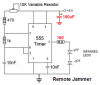
I am currently attempting to build a circuit for a TV Remote Jammer. I have all the parts, but i am having a little trouble reading the schematic. I am not familiar with the battery layout. The schematic in question: **broken link removed** The reason I am confused is because the circuits I am used to building have the ground and the power going to the battery. In the above schematic, the power, a 9v battery, only has a positive lead coming out of it, and the ground is at the bottom of the schematic. If anyone could help me out, I would appreciate it.
 
Your link doesn't work.
Why don't you save the schematic then attach it to your reply here??
 
The 180 ohm resistor limits the LED current to less than 4mA which is much lower than a signal from a remote control. I would change it to 27 ohms for 26mA.
 
i just re-looked at the schematics and realized the VR wouldn't have much of anything to do with the 180 ohm resistor.
 
The value of the 180 ohm resistor determines the LED current and its brightness.
The value of the pot determines the frequency.

With 27 ohms, the current in the LEDs is 0.7V/27= 26mA.
With 30 ohms the current is 0.7V/30= 23.3mA. Not much difference but much more than the original circuit.
 
Hi
yes Uncle $crooge write. out put frequency(f out) will effect by pot value
fout=1/ {ln(2).(470+Rpot+2000)10e-9} Hz
so by turning the pot u can figure out exact signal jam point
 
Like tazman2087, I'm new to electronics. (The ground = the negative terminal of the battery was a suspicion with me, too, not a fact.)

So, if the schematic starts with 9V, how did audioguru end up with 0.7V so quickly?
 
nyoo said:
So, if the schematic starts with 9V, how did audioguru end up with 0.7V so quickly?
The two diodes, the transistor and the 180 ohm resistor make a constant current source.
The two diodes in series have a voltage drop of 2 x 0.7V= 1.4V.
The base-emitter of the transistor has a voltage drop of 0.7V. Then the 180 ohm resistor has 1.4v - 0.7V= 0.7V across it. Ohm's Law calculates the current at 0.7V/180 ohms= 3.9ma.
 
Uncle $crooge,

I'm beginning to understand. You are concentrating 4 of the components, ignoring the other 9 in the schematic.

The datasheet for 1N4148 has a max Forward Voltage, V(FM), or 0.715V. The datasheet for BC557 has a max Base-Emitter On Voltage of -750 mV.
Is that where your 0.7V came from?

On the NTE30001 datasheet, the High Output is at I(F) = 20 mA. Is that how you chose the 27 ohms?

If so, how did you (how would I) know to ignore the rest of the schematic, to see if the resistor should be 180 ohm or 30 ohm? At this stage in my understanding, I would have thought I needed to account for all 9 volts.

Thanks a lot.
 
The current in the two 1N4148 diodes is pretty high at about 13mA so their total voltage is typically 1.5V.
the base-emitter voltage of a BC557 is typically o.65V when its collector current is 4.7mA.
Then the voltage across the 180 ohm resistor is 1.5V - 0.65V= 0.85V and the constant current is 0.85V/180 ohms= 4.7mA.

The 4.7mA is not affected much by the supply voltage since it is regulated by the voltage of the two diodes minus the base-emitter diode of the transistor.

Now that the datasheets show the voltage across the current-setting resistor is 0.85V and not 0.7V then a 27 ohm resistor would produce 0.85V/27 ohms= 31.5ma.
Your IR diode has a max allowed continuous current of 50mA so 31.5mA is fine.

Only the 555 IC has a supply voltage of 9V in this circuit.
 
Uncle $crooge,

Okay, this is a public forum. And I am trying to come to grips with my personal ignorance. Public vs. private. So I'm prepared to be told this is not the place (especially by tazman).

But, if it's okay to continue, I'd like to concentrate on that diode, and figure out why you're quoting 13mA and 0.7V.

Attached please find a small circuit. Please assume the diode is a 1N4148, and that V(dc) is 9V. If I (or you, more carefully) measured amps and volts across the diode, what would I get? And where do I look on the datasheet for confirmation of that?

Thanks.
 

Attachments

  • diode n resistor.jpg
    diode n resistor.jpg
    13 KB · Views: 264
The datasheet says that the voltage across a 1N4148 diode at room temperature with a current of 5ma is between 0.62V and 0.72V. So with a current of only 1.7mA then the voltage is typically 0.64V as shown on the graph.
 

Attachments

  • diode and resistor.PNG
    diode and resistor.PNG
    26.3 KB · Views: 312
Hi

Im not going to build the circuit but out of general interest, why bother with the two Diodes?

Current goes from collector to emitter if
Vbase < (Vemitter - 0.7)

I can see how this is done using the two diodes to form a current though the 560 ohm resistor when the 555 is in its trough and get 7.6 volts at the base; and when the 555 is at its peak there is 9 volts at the 560 ohm resistor so no current flows, no 1.4 voltage drop and no emitter > collector current.

But wouldn't it be a lot simpler [and cheaper] if you want the ~4mA to just stick a bigger resistor at the base and scrap the diodes?
0.004 = 9-0.7 / 180 + Rbase
4mA = 8.3 / 180 + Rbase
Rbase = (8.3/0.004) - 180
Rbase = 1895

Then the current in the base would be:
I = 8.3 / (1895 + 180)
I = 8.3 / 2075

I = 4mA exactly

Would that not be the same circuit but simpler and cheaper?

Thanks
 
The guy who made the Instructable doesn't know anything about electronics:
1) The current in the IR LEDs is much too low.
2) A constant current source feeds the LEDs when just a resistor would work almost the same.
 

Attachments

  • remote jammer.PNG
    remote jammer.PNG
    33 KB · Views: 536
Last edited:
Sorry for double post but my above suggestion wont work because the 1895Ohm resistor and LED's would be in parallel I belive?

However, again a more efficient and simpler method?

**broken link removed**
youll have to excuse my diagram made in paint
edit:
noticed an extra zero in the 8.3K resistor in diagram

Is there anything wrong with my thinking, it seems more logical and efficient to me. :)
 
Status
Not open for further replies.

Latest threads

Back
Top