Continue to Site

Welcome to our site!

Electro Tech is an online community (with over 170,000 members) who enjoy talking about and building electronic circuits, projects and gadgets. To participate you need to register. Registration is free. Click here to register now.

  • Welcome to our site! Electro Tech is an online community (with over 170,000 members) who enjoy talking about and building electronic circuits, projects and gadgets. To participate you need to register. Registration is free. Click here to register now.

Frequency divide by 15

Status
Not open for further replies.

L'ESPERANCE

New Member
Hi folks,

I have this 9vdc square wave (actually a 25% pulse) that I need to divide by 15 (not 16). This is actually a tach signal going from 600 to 6000 rpm hence 300-3000hz.

Is there a simple way to do this ? If it were 16, I'd look for a divide by N but I need FIFTEEN !


Best regards,

Denis
Grenoble
France
 
Hi Denis,
There are a few ways to divide by 15.
1/ Use a 4 bit counter (Such as a 74ls93) and decode a count of 15 and use this decode to reset it to zero.

2/ Use a preloadable 4 bit counter such as a 74ls161 and use the terminal count output (After inverting it.) to force a preload of 1

3/ Use two CD4017 counters. Configure the first one to divide by 3 and the second one to divide by 5.

None of these methods would give a 25% duty cycle output but this should not matter for your purpose.

Edit. You could also just buld a tachometer that will deal with the required number of pulses per revolution such as this one.

Les.
 
Last edited:
For a 50% duty cycle, two 4017 could be cascaded so the fifth output on the second one reset both and the first 7 outputs diode ored together to produce the output. Well 7:8 ratio which is pretty close.

Mike.
 
For the smallest number of ICs, ease of 9 V interfacing and ease of use, I don't think much would beat a CD4059

https://www.futurlec.com/4000Series/CD4059.shtml

A microcontroller would much smaller and cheaper, but would need programming and a lot more background knowledge to get it to work, and would need some interface to get to work with 9 V signals.

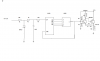
A third alternative would be to use a couple of 7490 ICs. The 7490 has two dividers, one that divides by 5 and one that divides by 2. You could use the divide by 5 in one of the 7490 ICs to divide by 5, leaving the divide by 3 needed. For the divide by 5, put the input in pin 1, the divided by 5 output will be on pin 11, and pins 2, 3, 6, 7 and 14 need to be grounded.

For the divide by 3, use the second IC divide by 5 input. You then wire the QB and QC outputs up to the R01 and R02 inputs. Then what happens is that the counter resets when it gets to 3, so that it counts 0, 1, 2 and then 3 for a vanishingly short time before going back to 0. You need the input (from the output of the divide by 5) on pin 1, the final divided by 15 output on pin 8, pin 8 also wired to pin 2, pin 9 wired to pin 3, and pins 6, 7 and 14 grounded.

(The 7490 is most often used as a divide by 10, where the first (fastest changing) output is QA. This alternative uses it as a divide by 5, so QA isn't used. The outputs used are QB, QC and QD.)

The 7490 ICs are only available with a 5 V supply.
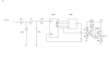
 
My thought would be something like a 74LS161 or 74LS163 (synchronous 4 bit counter) with a 3 input NAND gate connected to QB, QC & QD (not using QA).

The output of the NAND goes to the SR (synchronous reset) or LOAD input so it counts to 14 then the next clock pulse sets it to zero again.

Or, invert the carry out and feed that back to the LOAD input, loading with 1 so it counts 1...15 rather than 0...14
That could be done with a transistor or logic FET rather than a second IC.

However, you could use a 74LS13 in either case, one half as the reset or load gate and the other half as a schmitt trigger to "clean up" the input signal.
If only using as an inverter, sections of a 74LS14 hex inverter would work equally well and leave spares for other functions.


Either / any way from the above, the counter QD output is fairly close to a square wave, 7:8 ratio.

Datasheets:
http://www.calstatela.edu/sites/default/files/groups/Department of Electrical and Computer Engineering/labs/74161.pdf

http://www.applelogic.org/files/74LS13.pdf
 
Last edited:
I also vouch for the CD4059. I've used it to divide the frequency by arbitrary values, like 315 or 417, successfully.

One issue is that its output will not resemble 25% duty cycle, rather it is a narrow pulse.
 
Thanks for the many great ideas folks but I should add that I need the simplest IC-based circuit (no microcontroller) as all components will need to be MIL-STD to survive the harsh engine compartment environment.

Stuff that works on a test bench sometimes dies ...after a while ...at underhood températures ... ask me how I know that !

But I surely will investigate all your proposals.

Denis
 
MIL grade IC's still are out there, but they are getting harder to find. I'd start with TI. What does the divider output drive? Current, rise/fall times, etc?

To pass a datasheet audit, you might have to attenuate the input, use temperature-rated 5 v logic, then amplify the signal back up to 9 V.

ak
 
The input was to be limited to 9vdc with a zener. Should I use a 5V zener instead for digital IC compatibility ?
The source is ignition pulses from a coil negative : 12vdc with really big spikes (some at hundreds of volts) hence the zener amplitude limitation. I also use a simple lowpass filter to clean up the signal.
What is driven should get 12vdc pulses : one is a tach input, the other is a fuel pump relay "TURN ON" signal and also a fuel injection computer engine speed input. The last two are fed to a PIC or other µC. The tach is a classic analog VDO Mercedes tachometer.

I am tempted to use a CD4059 with a binary setting of the dividing value. The CD4059A is rated for 125C so no heat problem. It looks simple and reliable especially if I hardwire it instead of using DIP switches to set the 15 decimal value.

Denis
 
Last edited:
You need to have a series resistor if you are driving from the coil. If you don't the zener will try to pull the voltage down, and the negative pulse will be attenuated, stopping the spark and probably damaging the zener.
 
The 4059 needs protection from the vehicle's electrical system, but should handle the signal levels fine. The outputs are good for only a few mA, so you might need an output transistor buffer to drive multiple loads.

ak
 
Why not just a buffered or passive resistor divider from the original tach output voltage to your new tach

Any 4 bit. Counter with parallel preload and ripple carry out or count = 1111 can perform divided by 2 to 16 as already suggested. Simple
 
Last edited:
Aha! too simple Tony...Mercedes generates a so called TD signal from the ignition to drive the tach, the rpm input of the fuel injection computer and the fuel pump relay signal that says that the engine is running. In the event of an accident, the fuel pump is turned off by its relay if the engine does note generate that TD signal.

Do I need the 4059 - seems like overkill to me ? A 4040 can give me a pulse every 15 input pulses if I select 15 with the first 4 bits attached to pull up résistors. I would use an 4082 as the output NAND gate. The outgoing pulse would reset the counter to restart for another 15 counts. The outgoing pulse would also go through a transistor as an output buffer for the tach signal and the TD signal.
 
Last edited:
To Diver300 :
I would be using a 100K resistor at the input, then the zener and a simple resistive-capacitive low pass filter to send a signal to the counter.

Any suggestion for a simple but effective transistor ouput buffer/amplifier (5 volt to 9-12 volts) ?
 
Do I need the 4059 - seems like overkill to me ? A 4040 can give me a pulse every 15 input pulses if I select 15 with the first 4 bits attached to pull up résistors. I would use an 4082 as the output NAND gate. The outgoing pulse would reset the counter to restart for another 15 counts. The outgoing pulse would also go through a transistor as an output buffer for the tach signal and the TD signal.

There would be no point in having pull-up resistors on the 4040. The outputs go high or low without pull-ups. You could just join the outputs from the first 4 bits to the 4 inputs of one side of the 4082, and the output of 4082 should be connected to the MR of the 4040.

Q3 would give a near square wave output, and the output of the 4082 would give a very short pulse.

Even with the 4000 series ICs that will work at 12 V, you will probably want an output buffer to drive the circuits. A simple transistor buffer would be fine.
 
OK folks, please be patient, I'm just a rusty old amateur tech person.
Here is my schematic. The 12vdc to the circuit will be provided by a 12v regulated supply to eliminate transient noises. It will supply the 4040 and 4082 along with the ouput buffer.

That (stolen;)) output buffer part of the circuit was is originally powered by 9vdc, so the resistance values will need updating ? suggestions please ?

What do you fellows think ? I need something simple that will provide that strange TD signal that Mercedes requires.

BTW it's for a (Euro) 1988 500SEC that is getting digital ignition which cannot provide the standard TD signal ...

Denis
 

Attachments

  • td int.png
    td int.png
    16 KB · Views: 204
Makes sense and also makes counter parts count down to just ONE 4040.
What about the R values in the ouput buffer, are they OK as is or do they need tweaking ?

Denis
 
Ok the most recent version of my schematic (without the regulated 12vdc power supply).
Is 10K enough to limit that coil signal ?

Any comments, suggestions ? o_Oo_Oo_O

Denis
 

Attachments

  • td int.png
    td int.png
    16 KB · Views: 122
Although 1111% is indeed 15 decimal, remember that when the counter resets it starts from 0. So there are a total of 16 counts.
You require to decode 14. Which can be easily achieved with an inverter at Q0.
 
Status
Not open for further replies.

Latest threads

New Articles From Microcontroller Tips

Back
Top