Continue to Site

Welcome to our site!

Electro Tech is an online community (with over 170,000 members) who enjoy talking about and building electronic circuits, projects and gadgets. To participate you need to register. Registration is free. Click here to register now.

  • Welcome to our site! Electro Tech is an online community (with over 170,000 members) who enjoy talking about and building electronic circuits, projects and gadgets. To participate you need to register. Registration is free. Click here to register now.

Frequency divide by 15

Status
Not open for further replies.
Sorry, you are correct. If 15 resets the couter then effectivly 0 and 15 are on the same clock cycle and therefore reduce the 16 count to 15.

If however the reset only happens on a clock pulse then decoding 14 will work.

Mike.
 
Although 1111% is indeed 15 decimal, remember that when the counter resets it starts from 0. So there are a total of 16 counts.
You require to decode 14. Which can be easily achieved with an inverter at Q0.
Don't think so. The 4040 has a asynchronous reset, so the reset happens the instant state 15 is decoded. The reset happens at the *beginning* of state 1111, not at the end. The overall signal will be 15 clock pulses plus the time of the reset feedback loop, an additional 20 ns or so.

ak
 
So here is my latest schematic with an inverter on Q0.

Denis
 

Attachments

  • td int.png
    td int.png
    19.2 KB · Views: 95
1. Back up one sch; there is no need for the inverter.

2. You can delete R3.

3. What is the reason for that output stage?

4. Do *not* tie unused outputs to anything, especially 12 Vdc or GND.

5. If you don't have a 4082, it can be replaced by 4 diodes and a resistor.

6. The 4040 is a ripple counter, which means that all of the outputs do not change state at the exact same instant. This can lead to false reset signals coming from the AND gate. The case to cause this is the transition from 1011 to 1100. In theory, the outputs "ripple" from the least to the most significant bits, so the trailing 11 should change to 00 before the "4" bit changes from 0 to 1. 1101 to 1110 is another possible problem.

ak
 
Last edited:
OK, no inverter, no R3 and Q0 stays connected to the 4082 like so ...
I thought the schmitt trigger was a good idea for a clean signal but if I dont need it, what do you propose I put in ?
A simple one transistor buffer ?
 

Attachments

  • td int.png
    td int.png
    18.6 KB · Views: 102
The Q3 output should be a 47/53 duty cycle square wave, a nice clean CMOS output; no noise, and not a slow risetime, so nothing to clean up. It can source/sink only around 1 mA before the output starts to sag, so make sure you know what the output current needs to be in both the high and low states.

Back to previous posts by others, you can eliminate the AND gate altogether by using a presettable counter.

ak
 
Hmm.. I dont understand those presettable counters ... but I did simplify the output buffer stage with gain made adjustable by R1 if required.
 

Attachments

  • td full interface.png
    td full interface.png
    13.5 KB · Views: 95
OK here goes ...

What do others think about AnalogKid's reservations on the 4040 ?
Is another counter more suitable ? the 4069 looks like overkill...
 

Attachments

  • td full interface.png
    td full interface.png
    12.8 KB · Views: 98
I think that you mean that the 4059 is overkill. There's nothing wrong with overkill. None of the solutions suggested use all the functions of all the ICs, so all of them have some overkill.

There could be an issue with the ripple counter. A solution is an RC filter on the output of the AND gate, so that the output is delayed by a bit longer than the possible length of a false pulse, but still much faster than the shortest pulse length.

There is a variation of the scheme with the 7490 that gets over that problem.

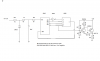
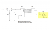
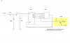
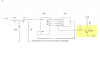
If you connect the clock input to ClkB, then QB, QC and QD will divide by 5. If you connect QC and ClkB to the two R9 inputs (pins 8 and 1) then that will divide by 3 with no danger of a race condition.

The count starts at 4 on the divide by 5 part when reset. (QD = 1)
The next high to low transition makes the output go to 0
The next high to low transition makes the output go to 1 (QB = 1)
The next high to low transition makes the output go to 2 (QC = 1)
The next low to high transition means that Clk and QC are both 1, so the counter is reset to 4 again.
 
I must be stupid but I dont understand how to use the 7490 to divide by 15 :eek::eek::eek:

Considering that my bandwidth is going to be 24 Hhz, would using a 4040 as shown in my previous diagram pose any real problems ? One advantage is that I can use regulated 12v power
instead of dealing with a 5V supply for the 7490...

Denis
 
You need to have two 7490s to divide by 15. You would only be using the divide by 5 parts of each 7490. One of those would be configured to divide by 3. The signal is then divided by 5 and then 3 to give a total divide of 15.

There is no problem running the 4040. Do you mean 24 kHz? A 4040 will go up to about 24 MHz at 12 V but it would be on its limit.

Don't underestimate how noisy car 12 V systems are.
 
I think I will first try my 4040 setup and yes, :oops: I meant 24kHz, my V8 at 6000 rpm emits 24000 pulses per second. A ridiculously low bandwidth for electronics...

I intend to use a 7812 with the usual capacitors and other capacitors at the chip Vss points.

This is an "ancient" 1988 Mercedes 500SEC that has relatively little digital electronics so spurious signals are somewhat limited.

But I understand your point.

Best regards
 
Last edited:
My concerns about the decoded reset signal having false spikes in it are relatively small. As above, a small R-C filter between the AND output and the Reset input will cover it, something like 1K in series and 0.1 uF from the Reset pin to GND.

Either the 4024 or 4040 should be fine.

ak
 
Status
Not open for further replies.

Latest threads

New Articles From Microcontroller Tips

Back
Top