Electro Tech is an online community (with over 170,000 members) who enjoy talking about and building electronic circuits, projects and gadgets. To participate you need to register. Registration is free. Click here to register now.
Welcome to our site! Electro Tech is an online community (with over 170,000 members) who enjoy talking about and building electronic circuits, projects and gadgets. To participate you need to register. Registration is free. Click here to register now.
That's because the reverse breakdown is only 20V. If you're driving a 12 coil to ground, you're going to see a minimum of 24V across that diode. You need something like a 1N4007 (1000V). I admit it can be a 1N4001 50V (1N4002 = 100V), but the higher the better, and any time I use a 1A diode, I use the 1N4007 as I only have to stock 1.
If it has to be schottky for quick recovery, use a 1N5819 (40V). That should work for a 12V system.
No, the peak reverse voltage across the diode is only 12V (same as the supply voltage, not twice the supply voltage). When the FET shuts off, the diode becomes forward biased, and conducts.
The turn-off time of the diode is unimportant. It should turn-on quickly, however.
In the OP's application, I also would have used a Si rectifier like a 1N400X. They are quite robust. The 1N58XX Schottkys seem to be less robust...
As for how to determine the reverse breakdown voltage required, I would use a safety factor of two to three.
I was under the assumption that your flyback diode should also be of around the same current/power rating (or more) as the inductive load you're driving.
I.e. if you were pumping 10 amps into a car ignition coil, you'd need a higher power dissipating flyback diode than if you were putting 100ma into a small relay on a PCB.
Correct me if I'm wrong but I've always designed anything I've made around this rule.
I was under the assumption that your flyback diode should also be of around the same current/power rating (or more) as the inductive load you're driving.
Agreed. The nature of inductors is that they try to maintain the current that is flowing when they are switched off. That current then flows in the freewheel diode at switch-off, albeit for a short time until it decays. But beefy diodes can withstand short-duration overloads. If it melts then it wasn't beefy enough
...The nature of inductors is that they try to maintain the current that is flowing when they are switched off. That current then flows in the freewheel diode at switch-off, albeit for a short time until it decays...
The current that was flowing through the load instantaneously begins flowing in the snubber diode as the FET turns off. The decay of the current flowing through the snubber diode is determined by the inductance of the load, the initial current, and the resistance of the coil. It is a classic RL circuit, with an exponential decay. A typical time-constant τ is likely to be less than 0.2s.
The diode current rating needs to consider the peak current, and how often the inductive load is switched on/off. On something like a relay that is cycled only occasionally, the diode will stand an occasional current pulse that is several times the average current rating. If the load is switched at rates of gteater than 10Hz, then the diode average current rating needs to be a half to a third of the peak current.
Nice Mike.You spotted a mistake in my drawing I redrew & uploaded the new one.The inductive loads current won't flow through Relay1. Its my drawing mistake.
Hanged means the logic signal gets stopped working.Not the relay contacts
Relay1 is in the same borad as where the logic circuit is.I used another relay to operate the EML because the Rel1 is too small.
**Note that the D2 diode is directly across Vdd & Vss is it ok? Will it absorb some spikes which goes to logic circuit?
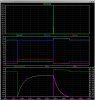
This simulation I did years ago shows why a snubber diode is needed. In the sim, there are three identical inductive loads being switched on-off by voltage-controlled switches. The red trace V(pulse) is the control signal that turns on all three switches. The switches are on when the red trace is positive +1v) , and off when it is negative -1V.
The bright green trace V(nodiode) is the inductive kick out of the unsuppressed coil. The high voltage developed as the coil turns off burns the points of the switch, and couples to nearby circuits, both capacitively, and inductively.
V(diode) lt, blue and V(hiside) dark blue shows the voltage with both a low-side switch and hi-side switch when the diodes are added. Note that with the low-side switching, the voltage across the opening switch is clamped one diode drop above 12V, while with high-side switching, it is clamped one-diode drop below ground.
Finally, the bottom plot panel is for Mike Odom, to show that voltage across the diode V(diode)-V(12v) dark green trace ranges from -12V (same as the supply voltage) to +1V (while the diode is forward biased by the decaying current). Note the forward current through the diode I(d1) pink trace starts at 3A same as the coil current I(L2) gray trace, but it decays rapidly to zero. The nominal 1A diode will have no trouble with an infrequent 3A short duration pulse...
Back to Suraj, your diode outlined in red has to be there to suppress rel2 (to prevent noise and to protect the contacts of Rel1). However, you still didn't answer the question about how you are suppressing the REAL inductive load, the one not shown on your schematic???
ya, that would be great if we lived inside a computer. Here's an o'scope shot of almost 30v developed by switching a 12v signal across a coil (5v/div).
This site uses cookies to help personalise content, tailor your experience and to keep you logged in if you register.
By continuing to use this site, you are consenting to our use of cookies.