Continue to Site

Welcome to our site!

Electro Tech is an online community (with over 170,000 members) who enjoy talking about and building electronic circuits, projects and gadgets. To participate you need to register. Registration is free. Click here to register now.

  • Welcome to our site! Electro Tech is an online community (with over 170,000 members) who enjoy talking about and building electronic circuits, projects and gadgets. To participate you need to register. Registration is free. Click here to register now.

Float Charger + Emergency switch

Status
Not open for further replies.
Here is the result. I removed the resis u said and didnt replace, hope is right
 

Attachments

  • image.jpg
    image.jpg
    1.3 MB · Views: 148
Hi,

Ok we are close now.

Three more changes (see diagram):
1. move end of wire 23-F to 24-F as shown with green arrow pointing right to left.
2. move end of wire 23-J to 22-i as shown with green arrow pointing left to right and up.
3. add jumper shown in blue.

Take another pic from top.
 

Attachments

  • wire6b.jpg
    wire6b.jpg
    246.6 KB · Views: 135
hi W,

Only a comment about using stranded wire as your links, its a very bad idea.

Strands will break off inside the fixing holes and cause internal shorts under the contact holes.

Use a tinned solid copper wire for links

E.
 
Like this?


Hi,


One more small jumper end movement as shown in the diagram.

You could test it after that final movement, and post a new pic too.

Yes as Eric says, solid wire is better, but dont change it over yet until we get this right :)
 

Attachments

  • Wire7b.jpg
    Wire7b.jpg
    268 KB · Views: 130
It works!! MrAl you are awesome, thank you so much. I attached pic of finished board. Now i have a lot of design work to do :)
 

Attachments

  • image.jpg
    image.jpg
    1.2 MB · Views: 147
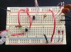
This is not what you want, but it is the setup I have that essentially performs the same purpose. It's easy. Control depends on a single DPDT mechanical relay.

I have a 3 stage charger for a 12 volt deep cycle battery. (The final stage is a float charge.)
The charger plugs into an electrical outlet. Thus, it is ON when the electrical power is ON.
I have a 120 volt coil DPDT relay. It plugs into an electrical outlet. (I bought the relay at Radio Shack.)
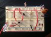
When the electricity is ON, the relay contacts are connected to nothing. (They can be connected to an indicator light.)
When the electricity goes OFF the relay contacts connect the battery to the LEDs.
I have a switch that allows me to control how many LEDs are running. 3 or 12. (More LEDs - more light - more current drain.) But the warm white LEDs I'm using draw less than 1 watt each.
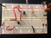
When the power comes back ON, the battery is disconnected from the LEDs by the relay.
And the charger which was OFF during the power outage is is powered ON and begins to to recharge the battery.
To test the system, I just unplug the plug that is connected to the relay. Yes. I could put a switch in there to do this. I haven't really seen a need for it.

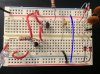
I'm currently working on an auto-cutoff to disconnect the battery from the LEDs when the battery voltage drops to a certain level. I'd also like to add a photocell to keep the LEDs from coming ON during the daylight hours. Both of these will require DC voltage. But they would only have to be powered when the charger is OFF.

The relay was about $10. The charger was about $30 (I already had it.) The battery I use is a 35 amp-hour deep cycle. But you can find them in a variety of capacities. I already had the 35 AH. I think it cost me $65. This same simple concept will work for any battery of any voltage. You just have to match the charger and the battery. I have it all in a small project project box - except for the battery and the charger.

I'm sure what you have will be more sophisticated. But sometimes simple works too.

Good luck with your project.

Bach On
 
Hi,

Yes a relay is not a bad idea, and a opto isolator is also a good idea. We could have used an opto isolator to send the signal to the detector that the AC is present.
 
It works!! MrAl you are awesome, thank you so much. I attached pic of finished board. Now i have a lot of design work to do :)

Hi,

You are welcome, and i am happy you finally got it working. As Bach mentions, there are other ways to do it too but i myself prefer the purely electronic ways with no moving parts.
 
Status
Not open for further replies.

Latest threads

New Articles From Microcontroller Tips

Back
Top