I think I did not explain this clearly.
I dont have the mixer above with the D701.
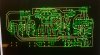
I just want the circuit I first posted inside this (http://rasteri.com/w/images/b/be/PMC-05PRO.pdf) unit that is powered with an 15V DC supply, the internal PS in that just makes 15VDC to 12DC.
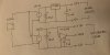
This is what my supply look like in the unit I where I want to use the positive/negative circuit.

Basically I need to do my own circuit that splits 15V DC to -7.5v +7.5v . Or 12DC to -6v +6v.
(If I understood it correctly).
Could also replace my external 15v DC supply to a 20V DC if this can give me -10v +10v. Have to adjust above circuit from 20V DC to 12V DC also if its needed.
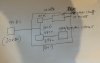
Something like this?

I dont have the mixer above with the D701.
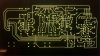
I just want the circuit I first posted inside this (http://rasteri.com/w/images/b/be/PMC-05PRO.pdf) unit that is powered with an 15V DC supply, the internal PS in that just makes 15VDC to 12DC.
This is what my supply look like in the unit I where I want to use the positive/negative circuit.
Basically I need to do my own circuit that splits 15V DC to -7.5v +7.5v . Or 12DC to -6v +6v.
(If I understood it correctly).
Could also replace my external 15v DC supply to a 20V DC if this can give me -10v +10v. Have to adjust above circuit from 20V DC to 12V DC also if its needed.
Something like this?
Last edited: