Continue to Site

Welcome to our site!

Electro Tech is an online community (with over 170,000 members) who enjoy talking about and building electronic circuits, projects and gadgets. To participate you need to register. Registration is free. Click here to register now.

  • Welcome to our site! Electro Tech is an online community (with over 170,000 members) who enjoy talking about and building electronic circuits, projects and gadgets. To participate you need to register. Registration is free. Click here to register now.

Feed AC circuit with DC?

Status
Not open for further replies.

Rorut

Member
Would it work feed this circuit with 12V DC?
Feed the IC pin8 with 12v an just leave pin4 empty?
 

Attachments

  • 1A25C1EF-CE65-45D3-B573-09F7C01875D6.jpeg
    1A25C1EF-CE65-45D3-B573-09F7C01875D6.jpeg
    302.7 KB · Views: 136
Nope I very much doubt that would work, the op amps need 2 supplies.
What you might be able to do is generate your own + and - 6v using your existing 12v supply, and run the circuit off that, so long as the op amps dont output large voltage swings.
 
The circuit will work *only* with DC supplied to the opamp power pins. If you think "VA" stands for volt-amperes, a common rating for a power transformer, you are misreading the pinout for connector CN7.

"VA" might imply an AC source, but the circuit requires two DC sources, one positive and one negative with respect to AGND. An AC input such as a direct feed from a power transformer will cause C650, C651, and *all* opamps to fail. My guess is that "+10VA" means +10V supply for analog circuits, in the same way that "AGND" means analog ground. The circuit needs +/-10 Vdc to operate correctly.

With a positive DC source connected between "+10VA" and "AGND", and pin 4 "empty" (not connected), the circuit will not operate correctly but probably nothing will fail.

Also, there are no decoupling components for any IC. Bad. Very bad.

Also, the schematic symbol for an electrolytic capacitor is incorrect by US standards.

ak
 
Last edited:
Im confused, could I feed it with DC -6V DC to pin4 and +6V DC to pin 8? If I do what you both suggest?
Thanks
 
I'm not saying it would definately work.
I was suggesting instead of having -10, 0 ad +10 power rails that you have -6, 0 and +6 rails, generating an artificial '0' ground rail with some circuit.
This might cause issues with other items in your system depending on how they are powered.
 
The NJM2069 operates off of +-4 to +-18 V supplies. **broken link removed**

+-10 is an odd voltage. +-12 and +-15 are more common.

Usually a center-tapped transformer with a bridge rectifier, and two regulators. e.g. LM317T adjustable. Linear, not switching supplies are preferrable for audio. You need some misc capacitors and resistors too.

You can buy a +-15V supply and regulate it down to +-10 with an LM317T. That regulator needs a 3V minimum margin.
 
The unit it is taken from is fed with an external AC supply.
I guess its converted internally to DC after that then.

But I will try figure it out and post something here for verification. Thanks a lot
 
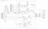
For all of the inverting amplifier stages, the non-inverting inputs are referenced to AGND. So are the two power supply filter capacitors. This is a clear indicator that AGND is the reference potential for both the signals and power rails. Because of this, the circuit will not work with a single power supply of any voltage. It requires bipolar supplies, such as +/-10 V (as indicated), +/-12 V, +/-15 V, or even +/-4 V, although that would limit the maximum signal amplitude before the onset of clipping.

The two supply voltages can be derived from a single voltage DC source, but they must appear at the connector as a plus voltage, a minus voltage, and a GND that is common for both. Since the circuit already has bulk decoupling (C650 and C651), this can be as simple as having two resistors in series between the +15 and its GND. The +15 connects to +10VA, the supply's GND connects to -10VA, and the junction of the resistors connects to AGND. NOTE - this works ***only*** if the +15 V supply output is completely "floating", with no reference to earth ground.

The two power supply voltages do not have to have the same magnitude. If you have supplies like +15 V and -9 V, the circuit should work fine. What is important is that the total of the two voltages is between the min and max values on the opamp datasheet.

In my experience, +/-10 V is more common in European circles than in the US. While not as common as +/-12, 15, or 18, I'd say it is one of the more common of the less common options.

Separate question: How is it that you are interacting with this board but do not have the correct power source? If the board already is in something, how is it powered?

ak
 
Last edited:
How is it that you are interacting with this board but do not have the correct power source? If the board already is in something, how is it powered?

ak
Thanks a lot for explaining. I dont understand everything but Im trying to.

In another thread I got help repair a Dj mixer (It had 15v DC supply).
This circuit is from the same brand but a newer version of the same model that has this send/return (FX loop) functionality. Its feeded with a 14v AC supply and is based on the same ICs NJM2068.

Really would like that functionality in the mixer that is repaired.

Repaired mixer schematic (15VDC)

Schematic on the mixer with circuit above (14VAC)
 
Page 7 of the second PDF clearly shows both a + and - half wave rectifiers feeding a 7810 and a 7910 regulators, respectively .
 
Here is the pcb for a model with 12DC, but can not find any schematic for it though. Same functionality just one earlier version. Using same ICs
 

Attachments

  • D852EFF5-00E9-4029-AE67-15FED7AD524F.jpeg
    D852EFF5-00E9-4029-AE67-15FED7AD524F.jpeg
    730.9 KB · Views: 98
"+10VA and -10VA" means the power supply is for analog, as well as "AGND" for analog ground. my guess would be there's also some digital circuits elsewhere in the same device, maybe some DSP chips, in which case you probably have +5VD, +3.3VD, and DGND for the digital circuits.


'
 
Page 7, upper right corner. This is the system power supply. It is intended to be fed by the secondary of an external power transformer, probably in a plug-in case called a wall wart. It uses a single-phase, non-center-tapped output. The two diodes (one facing each way) are half-wave rectifiers. Their outputs are filtered and go to older type 3-terminal regulators (7810 and 7910). The result is a regulated +/- 10 V supply.

A 15 Vac source is enough to drive this circuit. 15 Vdc will not work.

ak
1578014229647.png
 
Thanks a lot. I understand more but I still need it to run from the 15V DC supply (or a 20V external DC supply) that is used for the intended mixer. I need to learn how to do the dual rail/split thing with positive and negative from a DC source that you explained about earlier. Is it called something specific?
 
Last edited:
I need to learn how to do the dual rail/split thing with positive and negative from a DC source that you explained about earlier.
You can try to use an isolated DC/DC Converter.
DC/DC ( No Part that fit - only an Exemple !! )
The primary side could be taken to the IN of U 700 and AGND.

Such DC/DC Converters are availibe with symetrical Outputs too.

Then solder out D 701.
The positive connector of the output connect to AGND.
The negative output Pin connect to the IN of U 701.

Then Test if the 2 Voltages are symetrical.

I guess the better Variant is to use an DC/DC Converter with symetrical Outputs, because the output Voltages are shurely symetric.
Then solder out both diodes and take it to the Input of the DC/DC ( IN and AGND )
Decouple the Input Voltage with an Capacitator.
The output of DC/DC should be connected to the 2 Inputs of U700 an U701 and AGND.

For Protection i would solder in an Diode after the DC Plug to avoid damage about wrong polarity.
Than the thing should work with DC.
 
Status
Not open for further replies.

Latest threads

New Articles From Microcontroller Tips

Back
Top