Hey,
I'm building a 3 phase variable frequency drive for small (less than 2kW) motors. I've pretty much finished building a prototype circuit and everything is just dandy, except...
My IGBT's keep exploding. Badly exploding...
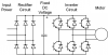
To try and isolate the problem I built an independant circuit that consisted of a 3 phase rectifier with my IGBT's across the DC bus (as in the picture attached that I found on wikipedia). I had no motor connected, and I had nothing connected to the gate terminal of the IGBT (so they were not being turned on). The IGBT's were rated for 600V 10A, and I was rectifying 415V AC (so it ended up 580VDC). When I flicked the switch they exploded. I had assumed that 2 of these IGBT's in series gave me a voltage rating of 1200V. Maybe not...
So annoyed and with a burnt hand I decided to try a lower voltage. This time I rectified single phase 240VAC (so it ended up 340VDC). This time I tested between the rails of the DC bus to make sure I didn't have a short, and the multimeter read 0.8Mohms. When I flicked the switch the replaced IGBT's exploded again.
I've tested the entire circuit using a 14VDC power supply as the DC bus and it worked well. Anything useful seems to make the IGBT's explode.
Does someone know what's going on here?
I'm building a 3 phase variable frequency drive for small (less than 2kW) motors. I've pretty much finished building a prototype circuit and everything is just dandy, except...
My IGBT's keep exploding. Badly exploding...
To try and isolate the problem I built an independant circuit that consisted of a 3 phase rectifier with my IGBT's across the DC bus (as in the picture attached that I found on wikipedia). I had no motor connected, and I had nothing connected to the gate terminal of the IGBT (so they were not being turned on). The IGBT's were rated for 600V 10A, and I was rectifying 415V AC (so it ended up 580VDC). When I flicked the switch they exploded. I had assumed that 2 of these IGBT's in series gave me a voltage rating of 1200V. Maybe not...
So annoyed and with a burnt hand I decided to try a lower voltage. This time I rectified single phase 240VAC (so it ended up 340VDC). This time I tested between the rails of the DC bus to make sure I didn't have a short, and the multimeter read 0.8Mohms. When I flicked the switch the replaced IGBT's exploded again.
I've tested the entire circuit using a 14VDC power supply as the DC bus and it worked well. Anything useful seems to make the IGBT's explode.
Does someone know what's going on here?
") ). The uppers need to be floating and your isolation method need to be able to handle the common-mode voltage you will see as well as your isolating drive signal being able to cope with being bounced by 1200V/us. A good OPTO can easily cope with that.
). The uppers need to be floating and your isolation method need to be able to handle the common-mode voltage you will see as well as your isolating drive signal being able to cope with being bounced by 1200V/us. A good OPTO can easily cope with that.