Continue to Site

Welcome to our site!

Electro Tech is an online community (with over 170,000 members) who enjoy talking about and building electronic circuits, projects and gadgets. To participate you need to register. Registration is free. Click here to register now.

  • Welcome to our site! Electro Tech is an online community (with over 170,000 members) who enjoy talking about and building electronic circuits, projects and gadgets. To participate you need to register. Registration is free. Click here to register now.

Egg Hatcher

Status
Not open for further replies.

artefon

New Member
Hello Guys,

im trying to create an egg hatcher using a pic microprocessor. Im going through a lot of trouble since im not used to circuit design. I want to create an egg hatcher that will check the temperature and activate a lamp to warm the hatcher. Besides that a motor will be activated periodically.

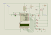
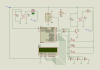
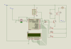
I started the schematic with a PIC16F88, a LM35 sensor, a LCD display and a stepping-motor. Is my schematic ok?

Comments and crits really apreciated
 

Attachments

  • chocadeira.png
    chocadeira.png
    38 KB · Views: 1,852
You need to have pull-down resistors on the three switches.
You need to have a stepper-motor driver IC between the PIC and the stepper motor.
Without an opamp amplifier between the LM35 and the A/D input, you will not have sufficient resolution in the A/D readings.
 
Hi artefon,

I suggest to use a 10 to 100nF decoupling cap at the analog input (AIN0).

A stepper motor can't be driven directly out of the MCU. You'll need a driver circuit.

I suggest to skip the stepper motor and use a DC-motor instead with two Hall-sensors signalling the right and left limit. Without counting the actual steps of the motor the egg turner will probably empty itself if the number of steps varies between left and right rotation.

I also doubt you can achieve a constant equally distributed temperature using a lamp. This will result in different hatch times and probably fry the eggs near the lamp.

A better way is using a small fan with air guides inside the incubator and a nichrome heating element in the downstream. Don't forget to add fresh air and vent holes in the incubator box to prevent the eggs from rotting.

Here is my design for an incubator controller. With the right arrangement of heater, fan and humidifier the hatch rate is expected to be 98 to 99%.

Boncuk
 

Attachments

  • INCUBATOR-CONTROL.gif
    INCUBATOR-CONTROL.gif
    37.1 KB · Views: 4,001
Thanks a lot Mike,

1) I added the pull down resistors.. are they ok?
2) I thought that the stepper-motor already came with a driver... should i go for a continuous motor?
3) Should i use the opamp with a 5 gain?

sorry for the dumb questions, im willig to get to the programming part ;)

Boncuk, only now i saw your post.. thanks a lot :)
I will study your suggestions and post an update.
 

Attachments

  • chocadeira.png
    chocadeira.png
    39.8 KB · Views: 1,121
Last edited:
They only have pullups and in the case of the 16F88 only on port B.

Mike.

He uses port B for the pushbuttons. So he could activate by switching to ground and have the I/Os internally pulled up. (saves about 5 Cents :) )

Boncuk
 
Last edited:
Thanks a lot for the help!

Actually im using PORTA so i'll have to use pull-down right?

About the opamp, is it really necessary? i could read values between 0 and 1 without it. What is the reason to use it?

Another update: Added relay for 12v motor.
 

Attachments

  • chocadeira.png
    chocadeira.png
    40.7 KB · Views: 778
The port pin cannot drive the relay, either. The port pin is only capable of sourcing ~25mA@ 3V; you will have trouble finding a relay that sensitive. You will need a grounded emitter NPN transistor, whose base is driven from the port pin through a current-limiting resistor; and whose collector drives one end of the relay, and where the other end of the relay is connected to 12V (not 5V). Depending on how much current the motor draws, you can probably just use the transistor to drive the motor.

The LM35 puts out 10mV per degree. If you use 5V to power the PIC, and if you set up the PIC's A/D so as it uses the 5V as its reference, the 10 bit A/D will quantize the range from 0 to 5V into 1024 steps, or ~5mV per step. That will allow temperature to be measured in ~ 1/2 degree steps. If that is good enough, then you can dispense with the opamp. If you set the opamp up with a gain of 10, then that will give you 20 A/D steps per degree.
 
Last edited:
He might as well narrow the A/D conversion to the required temperature range. Temperatures below 37.5deg/C are of no interest for an incubator. If he uses temperatures from 35 to 40 deg/C the resolution will be higher.
 
He might as well narrow the A/D conversion to the required temperature range. Temperatures below 37.5deg/C are of no interest for an incubator. If he uses temperatures from 35 to 40 deg/C the resolution will be higher.

Ergo, the opamp with a gain of 10, with offset adjusted to center the temperature of interest at 512 on the A/D
 
Last edited:
Hi Boncuk,
I have been search the internet for a home made incubator. I notice that your circuit cover all aspecs of hatching eggs. Rotating the eggs, circulation of fresh air, heating and humitifier to keep moister in the air to stops eggs from drying out. Will you be putting your design on the internet for others to build as well, for those that do not have the experince in designing there own. I'm interest as well, in building your incubator if it released as free a source.

Theo
 
Please read my PM.

Regards

Boncuk
 
i'm also builting my own egg incubator. i'm going one step at a time.

i have buitl the display, a "software driven SPI" 4 digit BCD display.
i'm using a 1-wire sensor, the popular DS1820. this gives 1/16th of a degree precision.
Driving it is a PIC16F876A.
It waits for a zero crossing signal, and uses a timer
to fire the heating element through phase control.
Complete PID routines are already at work.

To the moment i have only done PCBs for the display and for the Zero crossing display.
The rest is still in the breadboard and not even a schematic i have.
But it'sdone quickly just looking to the defines of the pins inside the asm file.

I´m stuck at this moment because my printer blew up.
at the moment i can't make any boards.
next step is to port out of the breaboard and run it some days long (no eggs inside).

off course this is the kind of project that will never be completely over,
because there will always be something more to add like
turning eggs, humidity control, logging, back up power. and so on...

best regards,
Hugo
Portugal
 
Hi Hugo,

I recommend using tendency recognition in your software to cut back heating power as the temperature approaches the preset value.

My design uses a combined 14bit temperature/humidity sensor (serial) with a maximum overshoot of 1deg/C on initial power up to stabilize to ±0.2deg/C at continuous operation. RH stabilizes to ±1%.

For a good hatch rate I recommend using all necessary functions to simulate a hen.

Boncuk
 
hi, Boncuk

though at the moment my design overshoots a litlle more than yours (about 3ºC), i have the Derivative part taking care of it. It uses a computer fan for forced ventilation. The setup is somehow like an air blower. the system stabilises in 20 seconds from cold start. Of course it takes time for the all box to be at setpoint temp but the air quickly goes out the fan at setpoint temp. so it overshots for 2 or 3 seconds.
I guess more tuning can be done when installed in its final box.

half way though development i came across one nice sensor which i will try in the future after this first setup as a chance to run. The SHT71 seems to me like a very nice upgrade. except it is not 1-wire, its "SPI alike", i guess. also is six times more expensive than the DS1820, but they are completely diferent.

A thing i'm worried about humidity is my present hability to only raise it, not for lowering it.
Raising it may be a must, since it need to be higher during the final days of hatching, but during the winter it may be necessary to reduce it, since outside humidity may be higher than needed for hatching.

I guess i will go as my inspiration dictactes ($$$$).
 
Last edited:
Hi Hugo,

you should look for the SHT11, which is the same as the SHT75, but doesn't have a male pin connector. It is much cheaper than the SHT75.

For a humidifier I recommend a so called "cold mister", used for small fountains as a decorative add on.

You might find them in aquarium shops.

Here is the PCB layout using the SHT11. Dimensions are: 31.75X22.5mm (1.25X0.8875")

Regards

Boncuk
 

Attachments

  • SHT11.gif
    SHT11.gif
    13.1 KB · Views: 479
  • SHT11-SILK.gif
    SHT11-SILK.gif
    8.4 KB · Views: 425
Status
Not open for further replies.

New Articles From Microcontroller Tips

Back
Top