ThomsCircuit
Well-Known Member
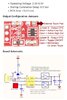
I can offer this file. I can configure it any way necessary.The current design produces a single pulse if the button is held down. If your touch switch produces a pulse, the pulse would need to be longer than the pulse incorporated in the design. Can you confirm how your touch plate output works in both latch and pulse modes?
eT
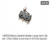
Some of my switches are on snap action roller type like shown. I have NOT ordered these yet. But this switch triggers a light for a door that is opened and closed. If you know of a switch that I could use in its place that works with your circuit that would be great.
I apologize if I'm being difficult. I will do everything possible to make this work.
Attachments
Last edited:
")
