Continue to Site

Welcome to our site!

Electro Tech is an online community (with over 170,000 members) who enjoy talking about and building electronic circuits, projects and gadgets. To participate you need to register. Registration is free. Click here to register now.

  • Welcome to our site! Electro Tech is an online community (with over 170,000 members) who enjoy talking about and building electronic circuits, projects and gadgets. To participate you need to register. Registration is free. Click here to register now.

Discussion: Rules For Drawing Readable Schematics

Status
Not open for further replies.
In the good old days when I would hand draw schematics which were to be made into formal drawings by "the draffies", wires which joined had a dot, wires which crossed either had the half circle bridge or a gap so that the crossing lines did not touch on the paper.

The draffies would then draw it correctly as per the appropriate standards and conventions, and everyone was happy.

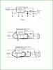
One place where the draffies and I differed, often very heatedly was depicting the internal layout of control cabinets.
The formal requirement was 3rd angle projection or some such thing.
My preference was to show the cabinet as though it had been opened out and layed flat on the paper.
The wireman could see at a glance were all the terminal rails and cable trunks were to be mounted. When the system got to the client, their technicials could see at a glance what was where to wire in the field cables and get it working.

JimB
 
I have never been in favour of this method, in this style termination dots are not used at all, but if a line crosses or terminates at a line without the half circle then it is deemed connected.
I much prefer the dot termination and straight line crossing.
Especially using drawings where each one uses one of these alternate methods.
Max.

I consider it a double-safety -- Use the "jumps" AND use junction dots. That way there is absolutely no doubt.
 
I consider it a double-safety -- Use the "jumps" AND use junction dots. That way there is absolutely no doubt.

Hi Matt,

I couldnt agree more on that point.

The point about drawing to the sense resistor directly is in contrast to being in favor of the four way cross with dot in another area on the schematic, which if we kept as a rule, we would have to do. The freedom to draw it to the resistor is an important point that is counter to always using a four way connection when possible.

My preference is also to use dots and half circle crossings, always.

On the lighter side of this, if your day is ruined then take the number of days ruined and divide by the sum of the number of days not ruined and the number of days ruined, then multiply by 100:
PercentDaysRuined=100*DaysRuined/(DaysNotRuined+DaysRuined)
which will also provide for a more balanced view on this :)

Instead of making a standard of some kind maybe we should make a list of all the issues first, then see what happens from there.
Here are some examples of why it's so hard to nail this stuff down...
Figure 1 is drawn in a 'standard' type way, while the others are drawn so as to show the significance of the proper parts placements and wiring points.
 

Attachments

  • SchematicExamples-001.gif
    SchematicExamples-001.gif
    48.4 KB · Views: 330
Last edited:
I consider it a double-safety -- Use the "jumps" AND use junction dots. That way there is absolutely no doubt.

I think everyone adopts a certain way of implementing this, Over the years I have developed the custom of single wire ended or crossing with a dot for connection and directly crossing (no 1/2 circle) for non connected.
Plus I not only deal with Electronic schematics but also N.A. style electrical drawings as per NFPA79, (Progress from Left to right, then down), but also European style electrical practice for drawings (progress down then left to right) as per EU.
So I tend to keep everything uniform for all situations and standards.
https://static.schneider-electric.us/docs/Machine Control/0140CT9201.pdf
Plus one of my main CAD tools is AutoCad for which I have a library of both electrical and electronic parts that conforms to both world standards.
Max.
 
Last edited:
The freedom to draw it to the resistor is an important point that is counter to always using a four way connection when possible.

Maybe it's just my tired brain, but is there some miscommunication? I was saying that one should try to avoid 4-way connections, not that they should be used when possible....?
 
Maybe it's just my tired brain, but is there some miscommunication? I was saying that one should try to avoid 4-way connections, not that they should be used when possible....?

Hi,

I had stated that making a four way connection with a single dot (rather than jogging the dots as you put it) is better than using more dots, so the rule was to minimize dots WHEN POSSIBLE. I stated that the exception would be when we have to show something special like a sense resistor wiring where we want the sense wires to go directly to the resistor. In that case jogging the dots should be applied so that the reader knows that the sense wires are connected to the resistor terminals rather than seeing them somewhere else on the drawing where there is a four way connection, just to save dots.

The drawings i posted are a little extreme, but that's how National Semiconductor chose to do it, and that's how variable this subject can be.

If this still isnt clear i'll post another drawing, no problem.

Ah, I see what you're saying. I still disagree with the 4-wires-one-dot idea though. If a schematic scanned in to the computer, or printed out improperly, or if the image quality is poor, then the dot may look like a jump (I've had that one happen before) or it may not show up at all. I think jogging is the safest and least open to misinterpretation. However, seeing as we have two entirely opposite opinions, I'd be curious to see what others think.

Regards,
Matt
 
Hello again,

Well i see your point and think it would be good to have that for poor diagrams, but i'd have to wonder how much this actually happens. I guess it also depends on what techniques are being used for the drawing and printing, etc. Back when i was in the industry we had to use special paper for the drawings, and the only way there could be a dot missing was if the draft was not done right. The ink was India ink. The dot size was uniform throughout the drawing too.
I could see someone doing a drawing in pencil though as we also did. In this case the draftsman has to know the importance of the dot.

Although i do agree partly with your point, i also see other views about this. One is that many drawings are obvious as to whether or not there is a connection or not. For the single stage common emitter transistor circuit given earlier in the thread, it is obvious that the two resistors on the base bias the base of the transistor meaning there must be a dot there, otherwise we would see two resistors in series connected between the positive rail and ground with the center node that just happens to cross where a transistor stage normally has two bias resistors connected :)
So sometimes the dot will also be implied, which reduces the number of cases where no dot looks ambiguous.

I think i vaguely remember one time in the past where the dot was missing and i could not be sure if it was there or not, but it was too long ago to remember what it was about now. Had the drafter used jogged dots would it show up? If he had known that there was a connection there then he would have drawn it jogged, but if he didnt interpret his copy correctly then he might draw it wrong anyway. So there are a of possibilities. Yes, if he knew it was there and drew it jogged then i would have had no problem reading it. But i think we have to weigh the overall appearance to the number of occurrences, and how significant it is if the drawing is wrong which would depend on the actual connection point and the impact of a wrong schematic on human or perhaps precious animal life. For my experience it would be a very small percentage. For the ex Space Shuttle it might have been more important though.
If we turned to drawing every schematic using jogged dots i dont think it would be as professional looking as if we didnt do it that way, but in the interest of human life i might tend to view this differently. Maybe that's why we leave some things up to the author.

So my overall opinion on this is that i think jogging the dots is not necessary, but in some cases i do agree it may be a good idea. Yes it is interesting to hear other members views on this too.
 
but i'd have to wonder how much this actually happens. I guess it also depends on what techniques are being used for the drawing and printing, etc. Back when i was in the industry we had to use special paper for the drawings, and the only way there could be a dot missing was if the draft was not done right. The ink was India ink. The dot size was uniform throughout the drawing too.
I could see someone doing a drawing in pencil though as we also did. In this case the draftsman has to know the importance of the dot.
Yes it is interesting to hear other members views on this too.

I can see when older systems such as Blueprints etc were either hand drawn and/or printed/photocopied on inferior paper etc there was room for vagueness, now with most s/w together with modern printers and plotters and the production and distribution of prints electronically has virtually eliminated any of the hard to read prints, at least that is what I have come to experience now.
Max.

Hi,

Yes things have changed a lot in electronics and drawing since back then, and even back then there were very few mistakes over the years. I remember one comical one though, where a new draftsperson started the job and instead of printing "Muffin Fan" to show that there was a fan known as a muffin fan that blows on a large transistor heatsink, they printed instead "Muffin Pan", and it gave everyone a good laugh.

So it also depends on who is doing the drawing. The ancient scribes that made copies of the oldest bible pages were said to get everything perfectly exact, because if they even made one mistake their cost was they would have to discard the whole copy no matter how much they had done already, and start anew.
 
... A lot of members can't afford the luxury of schematic software...

For those members who may not know, there are a number of free Electonic CAD packages. CadSoft's EAGLE is very popular and quite easy to get the hang of, especially if you just want to draw schematics. A free version for personal, non-profit use is at:

It runs under, Windows, Unix, and MAC OS X and can convert schematics into .png image files that, I think, would be handy for posting on Electro-Tech-Online.
 
Last edited:
If your Adobe reader is not opening in Firefox you should be able to correct this under Tools ---> Options
See image:
pdfReader.JPG
 
Hi Ian,

I don't know if you know, but there are a number of free Electonic CAD packages. CadSoft's EAGLE is very popular and quite easy to get the hang of, especially if you just want to draw schematics. A free version for personal, non-profit use is at:

It runs under, Windows, Unix, and MAC OS X and can convert schematics into .png image files that, I think, would be handy for posting on Electro-Tech-Online.
I'm talking about "Other Members" My cad package cost a fair amount of money!! I was merely suggesting for those who can't afford it..
 
When creating symbols for IC devices with a large pin count, eg. 100-pin part. Instead of making one huge box that covers the entire page, use sectional symbols or multi sections. As an example, for a microcontroller, create one section with the system wide resources such as the dozen power pins, oodles of ground pins, the system oscillator pins, reset, JTAG, etc. Another section might be the digital pin sections, and lastly the analog pins. For one of the Cypress parts I am using it has analog GPIO, and Digital GPIO, although you can use the GPIO's for either or, the layout of the chip is such that Cypress recommended which sections were best for analog and which for digital. So I followed this recommendation and it came out in such a way as all my analog stuff was nicely grouped as was digital. The other thing was it fit nicely on the page and was readable.
Below is a example of a part, the schematic is not completed but I hope you get the idea. Notice I grouped all my analog I/O to one block/section, what ever you want to call it. My apologies, it's a jpeg :nailbiting:

CypressAnalog.JPG
 
When size permits I sometimes take artistic license and try to provide some meaningful info in the symbol, not always, but do when I think it will benefit the reader.
Here is an example.

diffdriver.JPG
 
Nice work Mikebits. Getting library symbols right is hard work and time consuming, but once it's done it makes life much easier for everyone. Anything that helps makes schematics simpler, consistent, readable, and understandable gets my vote. Have you ever tried to figure out what is going on with schematics in car manuals? Way back I did a similar thing to you for the 555 timer and it helped a lot when designing with it. Having said that, I still like the hand-drawn circuits that normally start a design, and some of the circuits from the draftsmen 'on the boards' were works of art.
 
Last edited:
I still like the hand-drawn circuits that normally start a design, and some of the circuits from the draftsmen on the boards were works of art
It is funny... Although my schematic editor cost £££££ I still use paint... Like Mike I have a library of parts. I have one picture that contains a whole host of components with a white space at the top, After I draw a circuit using copy paste, I trim the page under the circuit and save as!!!
 
I do a similar thing, except using Word draw. Mind you, Microsoft have really made things difficult with their context sensitive menus.
 
Have any of you worked with Hierarchical Blocks ? I often see them being used in large complex designs with many pages. I would think they might be good for a block diagram type view, but for someone needing to debug a board or boards, following a hierarchical design might make it difficult. I have never used this method but curious as to what others may have done in this area. How do you push deeper into a block to see the components, especially in a paper version.

hierarchical.JPG
 
Status
Not open for further replies.

Latest threads

New Articles From Microcontroller Tips

Back
Top