Continue to Site

Welcome to our site!

Electro Tech is an online community (with over 170,000 members) who enjoy talking about and building electronic circuits, projects and gadgets. To participate you need to register. Registration is free. Click here to register now.

  • Welcome to our site! Electro Tech is an online community (with over 170,000 members) who enjoy talking about and building electronic circuits, projects and gadgets. To participate you need to register. Registration is free. Click here to register now.

Dimmer Circuit Emits Fire

Status
Not open for further replies.

heri

New Member
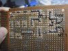
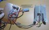
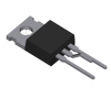
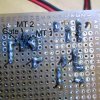
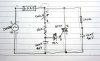
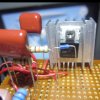
Hello you guys, thank you for accepting me here, right now I'm making a tool to dry the plastic filament, the unfinished part is the dimmer with a triac because MT 1 and MT 2 are on fire, like this has happened for the third time, then the input section exploded three times that caused the electricity at my house went out.

But this circuit works if I use breadboard but not veroboard, and this dimmer I combine with 555 timer IC (circuit diagram in figure 3 and figure 4b, https://www.nutsvolts.com/magazine/article/using-the-555-timer-ic-in-special-or-unusual-circuits). I do not know what caused it, hope you guys help me, thanks.
 

Attachments

  • bottom 2.jpg
    bottom 2.jpg
    222.4 KB · Views: 158
  • circuit diagram.jpg
    circuit diagram.jpg
    218 KB · Views: 151
  • top.jpg
    top.jpg
    206.9 KB · Views: 149
the electricity at my house went out.

What is your load? Is it more than your permitted house supply limit?

For the simple reason, that even if the "dimmer" is a Dead Short, the house supply cannot fail unless there is an overload.
 
Sorry if the words I use are not technical. I bought it in the local shop in my town, there are two types, the other is just the distance of the holes wider than the one in the photo attachment, is there any other type of board based on the electric current?

The breadboards are only warm because I only try a few minutes just to make sure they work or not. If the veroboard, as I recall, is not hot at all because just a few seconds after the fire out I immediately turn off the switch.
 
What is your load? Is it more than your permitted house supply limit?

For the simple reason, that even if the "dimmer" is a Dead Short, the house supply cannot fail unless there is an overload.
How to measure its load? I just use a heating element on a 300W hair dryer. My home power is 1300W, 220V.
 
How to measure its load? I just use a heating element on a 300W hair dryer. My home power is 1300W, 220V.
No its not!! More like 13200W.. The hair dryer will be 3000W... The BT triac is good for 8A... and 3000W requires at least 16A!!

You need to buy a 2N5445 or equivalent.... That circuit is for light bulbs..
 
Last edited:
I can't but help wonder if (a) there was residual flux between the solder joints, and (b) if the insulating distance between the veroboard is (much) less the breadboard (ie., the breadboard is providing more insulation between the joints than the veroboard). IIRC, the minimum spacing between opposite 240VAC traces is 6mm (.23 inches) or skipping 2 veroboard boards where the copper rings have been removed (as they will negate the insulating airgap).

This is providing the specs on the hairdryer and "home power" are correct. Something looks wrong there. In the USA, a typical 100A supply of 220V would be 22,000W. A 15A 120V breaker for a single circuit would supply 180W, just more than half of the 300W listed. At 300W the hairdryer draws either 2.5A at 120V or 1.25A at 220V, either way is not a lot.
 
Can I add two 'penneth .. .. ... ?

If I've read the datasheet for the BT137 correctly, that heatsink should be isolated ?

S
 
Sorry, the power in my house is only 1300W, and the power from the hair dryer is 300W.
Seriously? That's not enough to boil a kettle... Most houses have a 60A ~ 100A supply...A 300W hairdryer is the small, small, small one's you get for holiday!! I would still consider a larger triac though!!
 
Yes parts of russia cannot use a kettle without asking the neighbours.
Breadboard nor veroboard are really suitable for prototyping mains power.
 
How to measure its load? I just use a heating element on a 300W hair dryer. My home power is 1300W, 220V.
Please check your hair drier. 300W is not any load to trip the house supply.
Suppose the Drier is faulty, or a dead / partial short - then whatever your observations are is a good possibility.
 
Maybe in Rochdale; but I doubt they do in Semarang :).
Still!! 5A.... What could anyone do with that.. The man has a PC or laptop... My PC is 550W ... This has to be a flat or you couldn't have a brew and use the PC at the same time... Let alone dry you hair...
 
Willen one of the members was telling us a while back his incomming 'breaker was 5a or something really small, not everyone has the luxury of having a hefty domestic supply.
 
I apologise if I sound smug and arrogant, but I've to many places and seen quite a few installations..
If the OP has to work with such a limiting factor then far be it from me to judge...

I still think, however, A bigger triac would help..
 
As a first step then , Heri, it would be interesting to try the dimmer with a different load - an incandescent/filament light bulb of 40W or so if you have one.
In fact, we should check that the circuit is ok with no load at all - just in case there is a wiring mistake.

I agree that this type of varoboard is not the proper thing for permanent mains circuits, but it should work for prototyping something like that.
(I've seen 440V 3-phase on veroboard recently, and at least some of the items had not caught light).
 
By the way, how do you know I live in Semarang :nailbiting::D? For now it is not 1.300W of the smallest power in Indonesia but 900W.

I'm sure with the main power because I can use this circuit in breadboard. From this forum I got words like airgap and isolated, then also in other forums also similar like creepage distance, they suggested to bend MT2 forward of triac and removing un-needed pads in the high voltage area but i did it around the place . By temporarily trying this circuit once and the result does not emit a fire.

But I'm worried about this:

I agree that this type of varoboard is not the proper thing for permanent mains circuits, but it should work for prototyping something like that.
(I've seen 440V 3-phase on veroboard recently, and at least some of the items had not caught light).

because it will be on for at least 4 hours.
 

Attachments

  • dimmer 2 - bottom 2.jpg
    dimmer 2 - bottom 2.jpg
    585.9 KB · Views: 121
  • dimmer 2 - top.jpg
    dimmer 2 - top.jpg
    243.5 KB · Views: 119
  • triac.png
    triac.png
    11.9 KB · Views: 121
Last edited:
I agree that this type of varoboard is not the proper thing for permanent mains circuits, but it should work for prototyping something like that.
(I've seen 440V 3-phase on veroboard recently, and at least some of the items had not caught light).

I'm not sure I agree with this, as long as the proper steps and verifications are made.
From a purely materials stand point the circuit board material is the same between the veroboard and etched PWB and copper is copper.

Two items that need to be considered are: voltage clearances and current capacity.
1. Since the modification and picture in post 19 works, that empirically shows the issue was likely related to arching and clearance required for 220VAC was not met for post #1. The adjacent pads and unused pads of the original layout resulted in a violation of the clearances for 220V circuit.

2. The current capacity will be the next item to consider, track width and copper thickness dictate the current capacity. Copper width and thickness can be specified in order to meet the current requirements when having a PWB etched. The same is not the case for veroboard. What is the copper thickness (listed on the package) and trace width (likely have to measure) and does it meet the requirements? As shown in the picture in post #19, all connections have considerable solder which should allow for a few amps of capacity (as compared to 0.5 to 2 oz copper trace of the same width).
 
Status
Not open for further replies.

Latest threads

New Articles From Microcontroller Tips

Back
Top