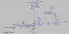
I am currently in the final stages of designing a USB Digital Oscilloscope but wondered if anyone knew why quite a few designs use the following circuitry and what its purpose is (image attached).
I have extracted this schematic from the BitScope designs which have been invaluable to the project so far but have also seen it used in PicoScope Digital Oscilloscopes.
I gather the series capacitor (C32) is for AC coupling (or short it out for DC), the 8pF cap is for some protection and D8 and D9 are for clamping but what is the purpose of the resistor voltage divider with capacitors and why is TRM1 variable? I also assume the two 510K resistors add in series to give your ~1M input impedance.
I would be very grateful for any help with working out this circuit!
Fred
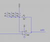
")