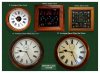
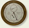
Just added a new slave to my masterclock system.
This is built in the style of a regulator and uses 3 modified quartz clock movements to display hours mins and seconds in a 12" office dial clock case.
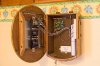
I found my master clock could only drive 3 clock motors using the 4093b chip. I was already driving 2 slaves from this output and as this new clock had 3 seperate clock motors I have now added a "repeater". The repeater sits inside one of my clocks and can drive upto 6 clock motors.
Full details here
**broken link removed**
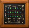
PS I have added a short animation showing the master driving an analogue and binary slave and electro mechanical chiming to You Tube
YouTube - masterclockmovie.mpeg