Continue to Site

Welcome to our site!

Electro Tech is an online community (with over 170,000 members) who enjoy talking about and building electronic circuits, projects and gadgets. To participate you need to register. Registration is free. Click here to register now.

  • Welcome to our site! Electro Tech is an online community (with over 170,000 members) who enjoy talking about and building electronic circuits, projects and gadgets. To participate you need to register. Registration is free. Click here to register now.

Digital Master Clock with 7 Seg LED Displays & Hourly Ch

Status
Not open for further replies.
Hi Brett,

So it seems a PIC design with the following specs' should suffice?

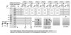
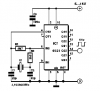
<1> 6-digit 7-segment display
<2> Crystal oscillator time-base with software 'trimmer' function
<3> 16 switch inputs (can include rotary encoders)
<4> 16 LEDs (can be used for lighted switches, indicators, etc)
<5> 4 relay driver outputs

Would you like to see the 1-chip or the 2-chip design (grin)?

Kind regards, Mike
 
Let me throw together a quick-n-dirty drawing... Hang in there... Mike...

<added>

ok, here 'tis... sorry it's so crude but I have to leave for work soon... uses all of the I/O pins so no speaker for those nice short beeps used for audible switch feedback and no PWM display brightness control...

Kind regards, Mike
 

Attachments

  • 1-chip_masclk.jpg
    1-chip_masclk.jpg
    71.2 KB · Views: 1,619
oliverb said:
Mike
Will this design be able to do the hourly chime or do you need an extra chip?
Bret.

You mentioned driving a relay for the Chime... The circuit above has four relay driver outputs... Again, forgive me for the crude drawing... Perhaps the MOSFET "TMR Relay Driver" in the drawing below will be better... Just imagine four of those connected to RA0 through RA3 for your relay outputs... Just change that 5v terminal to 12v if you're using a 12v relay...

Regards, Mike
 
Mike
Sorry Mike by the hourly chime I meant will it chime once for 1 oclock twice for 2 oclock etc.

I presume this is done in "software" on your chip as well as the 30 second pulse.

Brett.
 
oliverb said:
Mike
Sorry Mike by the hourly chime I meant will it chime once for 1 oclock twice for 2 oclock etc.

I presume this is done in "software" on your chip as well as the 30 second pulse.

Brett.
If you want it to chime that way then that's what you'd program it to do... If you decide you'd like 3 or 4 different options for the chime then you'd program it that way, perhaps using additional switches, or using a single switch to change chime modes and 4 LEDs to show you which mode you're in... The programming is the "smarts"... I hope I've stimulated your interest...

Kind regards, Mike
 
Dear sir
I want to build a big led digital clock with seconds display.kindly send me a full schematic diagrams of digital led clock.
 
Great master clock you have build there.
It is an excellent effort you mastered there and a fabulous end result.
I agree with you that the challenge of building something from standard IC's is a lot more fun than putting a PIC IC in it.
OK it's a lot of work but who cares, isn't electronincs a hobby anyway.
I have built about 7 * TTL clocks 10 years ago which serve very accurately in my place or family members places.
A lot of work breadboarding it all together with the 7447, 7490, 7413, 7408 and 7400 IC's.
The hardest part is the suppression of spikes on TTL, because the IC's themself create dips on the 5 Volts DC supply. so decoupling capacitors are recommended for each IC of about 100nF.
I take some pics and will post one or two of them later on.
 
Hiiiiiiiiiiiiiiiiiii how r u all iam a new member here i wish all the members to be my friends . i am studying computer engineering this semester iam taking digital logic design and my instructor want a project from me which is digital clock and i saw the schematics that attached here but they are soo complicated and she wants a simple digital clock so if any one like to help me in this project because really i need it and i will be thankful for him


thanks a lot
 
Hi Engineer SoSo

i can understand your condition. . when you get oppertunity to learn, really and sinerely do it. you may be comfortable in seeking help, as you used to seek as a child from parents. Now it is educatiuon for your brain to get trained and be able to take challenges in future. In the future , moment to moment who would help or spoon feed you-- sorry for this word-- just study with concentration and practice you will, i am sure excell in your academics and get ready for a higher education and even PHd whoknows?
please try to hardwork and practice the subjct my dear-- please don' get offended. there are, i am sure eminent personalities on this and sites like this. they could well solve or physically remove all your problems-- but is it REAL ??
all the best and look forward a brilliant expert in you

Sarma
 
Hi mvs sarma

i want to tell you iam not the person who depends on others i try all the time to do every thing by my self . iam just saying that i need a help from who can and iam sorry for this word i dont need it from you . just this

thanks alot
 
Engineer SOSO said:
my instructor want a project from me which is digital clock and i saw the schematics that attached here but they are soo complicated and she wants a simple digital clock
The clock circuit here is SIMPLE! It is a clock and a clock circuit is fairly complicated. It uses gates and counters and LED drivers. A watch uses one IC that does all that stuff.

Make a circuit that uses fewer parts, an LED Chaser maybe. Then tell your teacher that the blinking LED is counting and displaying the seconds.
https://www.electronics-lab.com/projects/games/003/index.html
 
32.768Khz ??

How did you generate a time base using 32.768Khz ? I think you must have divided it till 1Hz ...
I am right now looking out to select an appropriate crystal frequency to generate either 50Hz or 60Hz accurately. any idea ?
 
You can do this with one IC, a CD4521 and a 4.194304MHz crystal will do.
 

Attachments

  • 1 Hz.PNG
    1 Hz.PNG
    7.3 KB · Views: 8,412
I have added a 1 sec electric clock motor drive pulse to this clock (taken from the 2sec ootput). This will drive quartz clcok motors and will sync them to the main display.

I have used this drive along with the 30sec pulse to drive a couple of large 12" dial clocks I have made.

The clock steps on 1/2min when the second hand hits 00 and 30 secs.

This drive can be used for adding calender, moonphase, tide etc displays to clocks.

The quartz clcok motors have their quartz driver cct cut out. The drive wires from the master clock connect direct onto the drive coil.
Brett.
 

Attachments

  • secs.jpg
    secs.jpg
    61.4 KB · Views: 759
  • DIALQUAD1.jpg
    DIALQUAD1.jpg
    106.7 KB · Views: 575
Last edited:
New chime

I have now built a larger bell unit. This is wired remote from the master clock and hidden in my hallway inside a real longcase clock with the chime turned off (1 less clock to wind).

I have used a large 4" longcase clock bell. The bell is struck by a Franch clock hammer attached to the armature of an old 30sec clock movement.

The bell is turned off at night from the switch in the master clock.

The chime is now fed from the 2sec output as the larger bell takes longer to ring out.

I have added a thermal fuse to the coil of the 30sec clock just in case it gets too hot.
Brett.
 

Attachments

  • chime.jpg
    chime.jpg
    32.8 KB · Views: 543
Status
Not open for further replies.

Latest threads

New Articles From Microcontroller Tips

Back
Top