Continue to Site

Welcome to our site!

Electro Tech is an online community (with over 170,000 members) who enjoy talking about and building electronic circuits, projects and gadgets. To participate you need to register. Registration is free. Click here to register now.

  • Welcome to our site! Electro Tech is an online community (with over 170,000 members) who enjoy talking about and building electronic circuits, projects and gadgets. To participate you need to register. Registration is free. Click here to register now.

Digital Fat Calliper Sensor

Status
Not open for further replies.
If you connect PB0-1 to PORTB and PE0-1 to PORTA bits 0..3 then code similar to the following can be used to read the calliper value. PE0-1 will need pull-up resistors.
Code:
#include <stdint.h>

const uint8_t pow2[8] = {1, 2, 4, 8, 16, 32, 64, 128};

uint8_t readCalliper()
{
    nRBPU = 0;            // enable weak pull-ups on PORTB (register bit name may be different)
    
    TRISB = 0xFF;        // all PB0-1 floating high
    PORTA &= 0xF0;        // get ready to pull low on PE0-1

    // first try pulling each pin of PE0-1 low in succession
    for(uint8_t i = 0; i < 4; i++)
    {        
        TRISA = (TRISA & 0xF0) | ~pow2[i];    // set a single bit as output (forced low)
        delayus(5);
        
        uint8_t pv = PORTB;
        if(pv != 0xFF)
        {
            for(uint8_t j = 0; j < 8; j++)
            {
                if(!(pv & 1))
                    return i * 16 + j;
                    
                pv >>= 1;
            }
        }
    }
    
    TRISA |= 0x0F;        // all PE0-1 floating high
    PORTB = 0;            // get ready to pull low on PB0-1
    
    // now try pulling each pin of PB0-1 low in succession
    for(uint8_t j = 0; j < 8; j++)
    {
        TRISB = 0xFF & ~pow2[j];
        delayus(5);
        
        uint8_t pv = PORTA;
        if(pv & 0x0F != 0x0F)
        {
            for(uint8_t i = 0; i < 4; i++)
            {
                if(!(pv & 1))
                    return i * 16 + 8 + j;
                    
                pv >>= 1;
            }
        }
    }
    
    return 0;        // no valid reading
}


Hi Doug,

Thanks a lot for your reply! :eek:

Vivian
 
Hi,

2012-10-22-175.jpg

Can anyone tell me what is the display used in the digital fat calliper? Is it a 7segment LCD display? If I choose 20*4 character LCD display as my display, can it show same thing as the display used in the digital fat caliper?


Vivian
 
Can anyone tell me what is the display used in the digital fat calliper?
It's a custom made LCD.
If I choose 20*4 character LCD display as my display, can it show same thing as the display used in the digital fat caliper?
A 20*4 character display will display 4 lines of 20 characters. You would be the best judge of whether it fits your needs or not.
 
Hi,

I want to ask, if I want the user to input their data (eg: age, gender), then which display is more suitable to use?

Vivian
 
Hi,

Here is my draft for the connection of the electronic component to the microcontroller. Can anyone help me to see is it correct?
Thanks.
Untitled.jpg

Vivian
 
How can I show the input data such as age and gender(user set it) in the LCD display? And the input data will then be substitute into the body percentage equation. And the result will then appear at the LCD display.
 
I want to ask, if I want the user to input their data (eg: age, gender), then which display is more suitable to use?
I don't know how to drive the custom LCD, so I'd personally use either a character LCD (e.g. 4x20 as you've mentioned) or a graphics LCD. If I had a driver for the custom LCD (and sufficient pins on the microcontroller), I'd use that as it seems to have all the info (age, weight, gender, height? etc.) you need.

Here is my draft for the connection of the electronic component to the microcontroller. Can anyone help me to see is it correct?View attachment 71789
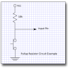
In general, when using pullup resistors for switches it should look like this:
pullup.png

Depending on the LCD you use, you may find you need more pins than you will have available with your current pin usage in your schematic. You can gain additional free pins by multiplexing your additional switches and LEDs into the existing calliper matrix. You could therefore connect all 4 switches and 4 LEDs using only 1 pin rather than 8.

How can I show the input data such as age and gender(user set it) in the LCD display? And the input data will then be substitute into the body percentage equation. And the result will then appear at the LCD display.
You have 3 buttons; I assume they are: Mode/Select, up, down. On your LCD screen (assuming 4x20 character LCD) you can write the words: "Age: ", "Sex: ", "Weight: ", "Height: ", etc. Pressing the 'Mode/Select' button would move the LCD cursor (a black or flashing block) to the appropriate point on the screen. Pressing the 'up' or 'down' buttons would adjust the value at that appropriate point. You will have to put these functions into the code of the PIC microcontroller.
 
Hi Doug,

Thanks for your reply. Do you have any suggested website which can learn the way to program the 3 button as you have mentioned? Because I not very know about the programming, so I need to do some reading on it.
Thanks.


vivian
 
Hi Doug,

I want to make 1 of the switch can have two function, which it can function as 'enter' and 'on/off'. Is it possible??

Vivian
 
Is the connection of pull-up resistor for PEO-1 is correct?
No, you have drawn series connected resistors. Pullups resistors will connected from the microcontroller pin to VCC, as per the switches.
I want to make 1 of the switch can have two function, which it can function as 'enter' and 'on/off'. Is it possible??
Yes, it's possible. In your program you can perhaps write it to turn off if the enter button is held for 2 seconds, for example. You might also want it to turn off if it's not used for a minute or two.
 
Hi Doug,

That means all the pull-up resistor need to connect as same as the connection of pull-up resistor for the switch?

Vivian
 
That means all the pull-up resistor need to connect as same as the connection of pull-up resistor for the switch?
Yes
Please help me to see is my connection is right. Thank you.
Looks good. Because you wish to have a software ON/OFF function, you need to be able to shutdown all external devices that draw current, e.g. LCD. You can power the LCD via one of the microcontroller pins; a suggestion would be to use a series 100 ohm resistor from the microcontroller output to the LCD VCC (and the positive side of the potentiometer) in addition to a 100nF capacitor across the LCD VCC/GND pins.

Is there any reason you have a crystal oscillator attached? If you don't need high timing accuracy, you can just use the internal oscillator of the PIC (8MHz-125kHz adjustable range 1% accuracy).
 
You can power the LCD via one of the microcontroller pins; a suggestion would be to use a series 100 ohm resistor from the microcontroller output to the LCD VCC (and the positive side of the potentiometer) in addition to a 100nF capacitor across the LCD VCC/GND pins.


lcd.jpg
Is this what you means?

Vivian
 
Hi,

Actually I still not very clear about the working of charlieplexing in the pincher. Anyone can explain to me?
Between, how I can get the thickness of the skin from the pincher? How should I program it? And also how to program the microcontroller because I need to input equation into the microcontroler.

Thanks.


Vivian
 
Hi Vivian,

Those are all good questions. This is not a simple project, but it can be made a little simpler by going at it in steps. Get a prototype that gives a number related to skin fold thickness. Then develop that further to improve the user interface and add more "bells and whistles."

There are several project management techniques, such as flow charts and fish diagrams (aka, critical pathway). I prepared a hypothetical critical pathway chart for you. I am sure it is incomplete and has errors. It is just a rough example of how to approach something that has so many possibilities and potential paths as this project has.

View attachment DigitalFatCaliper.pdf

I suggest that you look at it, decide what really needs to get done first, and put some of the other things on hold.

Let's take the charlieplexing and pincers thing. Absolutely, you will need to know how that is wired at some point. But, do you need to know that before you get your feet wet in programming? Similarly, for programming, a very simple program would give you the pincer opening and/or fold thickness without all the data entry refinements you have mentioned.

I suggest that you get a feel for microcontroller programming first or develop a collaboration with someone who already knows how to do that. (If you use a chart like I show here, add that collaboration to it.)

As for the pincer and charlieplexing, I do not think an accurate schematic can be made with the information we have. Can you get local help? How far are you from Northeast USA, Australia, UK, or anywhere there might be a local member of ETO who could help determine the actual circuit for you?

To reiterate, if you are planning to do the programming yourself, I do not think the actual circuit for the pincer should be your focus right now.

John
 
Hi John,

Thanks for the reply. I stay at Malaysia, and Malaysia do not have the manufacturer for digital fat calliper, so it is hard to find local help.

Vivian
 
Status
Not open for further replies.

Latest threads

New Articles From Microcontroller Tips

Back
Top