Continue to Site

Welcome to our site!

Electro Tech is an online community (with over 170,000 members) who enjoy talking about and building electronic circuits, projects and gadgets. To participate you need to register. Registration is free. Click here to register now.

  • Welcome to our site! Electro Tech is an online community (with over 170,000 members) who enjoy talking about and building electronic circuits, projects and gadgets. To participate you need to register. Registration is free. Click here to register now.

Digital Clock(Big)... Using PIC

Status
Not open for further replies.

Ayne

New Member
I am going to make Big Digital Clock Using PIC.
Big mean it's length will be 2 feet approx... and it will be wall mount.
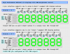
Schematic
**broken link removed**

**broken link removed**

Plz see the picture carefully and
All type of suggestions are welcome.
Which function u like to be in this Clock...

I am in hurry now... and will discuss it later..

Thanks.
 
Hi Ayne,

(1) I wonder if your 4511 and your 7405 devices can source and sink the 'peak' current required to drive the displays to full brightness at a 1/6th duty cycle?

(2) What are the voltage/current ratings for the large 7-segment displays you plan to use? Some of the really large displays use series LEDs to make up the segments and you may need a higher source voltage.

May I offer an alternative driver method (below) for a full brightness display with PWM brightness control and fade-to-black capability? This method uses 8 I/O pins, common anode displays, a single MIC5821 8-bit serial-to-parallel 500-ma sinking driver IC, and 600 to 800 ma PNP source drivers.

Have fun and good luck with your project.

Mike

**broken link removed**
 

Attachments

  • Matrix 7-Segment.PNG
    Matrix 7-Segment.PNG
    48.4 KB · Views: 3,936
Last edited:
Mike said:
This method however uses common anode displays instead of common cathode displays.

Just wondering why common anodes are used, could you not use common cathodes, or was it just because you had them on hand?

I'm mostly curious about the dimmer function, and scoping out its features/requirements.
 
I am attaching two Picture...
Want to know that which is the best way way ???

**broken link removed**

**broken link removed**

For knowing 4028 and 7405 see my first POST(Pictures)..

Thanks
 
Ayne,
If you are going to use the large (four inch high) seven segment displays such as Kingbright SA40-18EWA then you need about an 8 volt supply to light them as they use 4 leds in series for each segment.

If you want larger digits then you could have a look at the five inch 7SR50011AS (about twice the price of the 4 inch type though) and they need about 9v supply.

Or you could make your own displays or use ready-made modules.
 
I am going to make my own 7-Segment Display...
All LEDs will be parallel in it and i will use 5volt...

Below is the circuit.. I never parallel LM7805 before.
I want to increase current.. This technique will work!!!... I am using LM7805 because thisa is only available in our local market..
Resistor i use is 0.33 Ohm

**broken link removed**

Need improvement??
It will work??

Thanks in advance.
 
No, the regulators will not work properly in parallel because the will not share the load equally.
If you really want to stick with using 5v for the displays then an old pc at or atx switch-mode power unit may be a better solution because it would be far more efficient at high current and very cheap.
 
You can't drive the multiple led segments directly from the 4511 chips because their absolute maximum current per output is only 25mA.

The Sparkfun design uses an uln2003 driver which contains seven transistors each rated at 500mA and I think it also uses a 12V supply for the pairs of led light bars.

You will need to either use one of those chips or 7 discrete transistors to do the same thing.
 
In an earlier diagram, you show 2N3904 and 2N3906 as current switches. Although they can withstand 200 mA before blowing up, these transistors are not suitable for current over 100 mA. And with your base drive of (<0.5 mA), their saturation current is only about 5 mA.
 
Ayne said:
I am attaching two Picture...
Want to know that which is the best way way ???


For knowing 4028 and 7405 see my first POST(Pictures)..

Thanks
Well, using transistor drivers would take care of 'peak' current concerns but you probably want to use heftier transistors like 2N4401 & 2N4403.

Using an NPN column driver in the 2nd circuit is probably not a good choice. A PNP would be better but then you'd need active low signals and your 4028 is active high. Perhaps a 74HC138 3-to-8 line decoder would be a suitable replacement for the 4028 and you'd have an extra pin left over.

The 1st circuit with the 74LS05 open-collector IC driving a PNP column driver transistor would allow you to use higher voltages if you decide to try those super size 7-segment displays which have several LEDs in series for each segment. I believe the new white and blue displays also require higher voltages.

You mentioned in a subsequent post that you were considering operating multiple LEDs in parallel for each segment. I'm not sure that's a good idea since it would increase the 'peak' current demands.

Those two transistor circuits show common anode displays but in a subsequent post you're showing common cathode displays. Have you decided which type display you're going to use?

Take care. Mike
 
gramo said:
Just wondering why common anodes are used, could you not use common cathodes, or was it just because you had them on hand?

I'm mostly curious about the dimmer function, and scoping out its features/requirements.
The hardware dictates the choice of common anode displays. I simply haven't found any 8-bit serial-to-parallel sourcing drivers similar in function (and current capacity) to the MIC5821 sinking driver and I didn't want to use 2 chips.

The PWM brightness control uses a PWM period equal to the column 'scan' rate. Brightness is inversely proportional to the PWM duty cycle; 5% PWM = 95% brightness, 100% PWM = 0% brightness. If you enforce a minimum PWM duty cycle setting you can use the Port B column driver bus as a data bus to load the MIC5821 shift register at the beginning of the interrupt cycle when the display is off (before the PWM signal goes low -> display on). When using multiple MIC5821's in a large matrix display you simply throw 8 bytes in a row onto Port B with a Clock pulse after each byte at the beginning of the interrupt cycle to load all of the 5821's in parallel in about 4.8-usecs. ISR 'overhead' for driving a large 512 LED matrix (eight 8x8 matrix displays) is approximately 5% with a 20-MHz clock (50-usecs each 1.0-msec interrupt cycle) and the algorithm should port over to C or your favorite BASIC without difficulty. A minimum PWM setting of 1-2% provides plenty of time for loading the shift register(s) at the beginning of each interrupt cycle.
 
Last edited:
I should mention that we can take advantage of the column driver bus (only 1 pin is ever low at one time) to implement a simple single-pin column driven switch matrix, if you don't mind a few 1N4148 diodes, where you sample each switch once every six or seven interrupts (depends on how many display columns you're scanning).

If you're using 1.0-msec interrupts this provides a very crude 6 or 7 msec 'debounce' and the code is incredibly simple (the SWKEYS variable is "live" switch press data);

Code:
;
;  refresh switch input from column driven switch matrix (one 
;  switch tested each interrupt cycle)
;
;  COLPOS is our column position ring counter which will contain one
;  of the following values; 00000001, 00000010, 00000100, 00001000, etc.
;
;       comf    COLPOS,W        ; example ~COL3 = 11110111        |
        andwf   SWKEYS,f        ; indicate switch 'off' (0)
        movf    COLPOS,W        ; example  COL3 = 00001000
        btfss   SWInput         ; is switch at COLPOS 'on' (0)?
        iorwf   SWKEYS,f        ; yes, indicate 'on' (1)

** Yes Gramo, please feel free to show us the Swordfish BASIC equivalent (grin)...
 
Last edited:
picasm said:
You can't drive the multiple led segments directly from the 4511 chips because their absolute maximum current per output is only 25mA.
He can but since he's still multiplexing them the "average" current and brightness would be quite low. But if he's considering throwing that many chips into his 'solution' he could always use 74HC595's or some other "latch" with 25-ma outputs and he'd have a nice bright nearly 100% duty cycle display...
 
Last edited:
Mike said:
He can but since he's still multiplexing them the "average" current and brightness would be quite low. But if he's considering throwing that many chips into his 'solution' he could always use 74HC595's or some other "latch" with 25-ma outputs and he'd have a nice bright nearly 100% duty cycle display...

Mike,
I agree with you that the 25mA port limits would be ok for a small multiplexed 7-segment display.
But as the OP wants to make his own very large display, I assume he will need many leds per segment, and I don't favour his 5v supply requirement.
I would be happier if the drivers were able to handle about 500mA, at least it would help protect the chips during the software development stage if he had any multiplexing errors etc.
 
Thank Mike, K8LH and others.

Mike, K8LH as u suggest... Picture has been modified.. Now i am going to use "74HC138".

**broken link removed**

Now i need ur help.
First little detail.
I am going to use 12 volts for driving Large 7 Segment Display.
For boosting the current after IC 4511 i am going to use "ULN2003"..
some thing like this:
PIC I/O---> IC 4511 ----> ULN2003 -----> Big7 Segment display.

But the problem is, what i use after 74HC138 for boosting the current for driving the Big 7 Segment.
I mean:
PIC I/O---> IC 74HC138 ----> ?????? -----> Big7 Segment display.

Hope u can understand.

Thanks in advance.
 
Now the complete Circuit..
**broken link removed**

I want to know from senior membors which will be the best choice for P-Channel MOSFETs for this knid of application.

C & C are welcome.

Thanks in advance..
 
Status
Not open for further replies.

Latest threads

New Articles From Microcontroller Tips

Back
Top