Chris_P said:
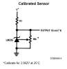
Me again, its taken me a while to make a waterproof LM335 sensor and get another digital thermometer to make some comparisons. Readings are pretty close but I think I would like to try these recommendations above. I have modified the drawing Len did for me and attached it to show what I have and what I think Leftyretro is suggesting.
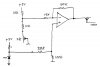
What I am not sure on, (more stupid questions) what resistors do I need to change to change the gain from 5X to 10X? And what would be a suggested value for the 20 turn trimpot on the output?
If this circuit is correct how would I calibrate it properly? ie how would I set the "zero adjustment" pot and the "range pot"?
To double the gain, you could double the values of the two 100k resistors.
If you connect one end of your output pot to the opamp output and the other end to ground and take your output from the center "wiper" of the pot, any relatively-high value pot should work. With the wiper centered, you would get half the opamp's output voltage swing. Higher resistances generate more noise. So you probably won't want to go overboard; probably something between 10k and 50k would be OK for the pot. Also, your opamp's datasheet might have information about what resistance is best, on its output.
For calibration, someone else will probably have the answer. But conceptually, if you had a signal generator that could produce a waveform with your 1V p-p amplitude, and also provide a DC offset so that the signal generator's output was covering the same range that your temperature sensor would cover, then you could just connect the signal generator in place of your sensor, connect your circuit's output to an oscilloscope, and adjust the pots until the output was covering 0 to 5 Volts. Actually, such a signal generator could be easily and cheaply built, with another opamp or two (and in many other ways).
By the way, there is some very good basic information about the common opamp topologies in
https://www.electro-tech-online.com/custompdfs/2007/06/AN-20.pdf and
https://www.electro-tech-online.com/custompdfs/2007/06/AN-31.pdf .
You might also want to go to
http://www.analog.com and search for AN-273, if you think you might need to use a long cable run, and/or might need to combat the effects of RF noise.
In your circuit, I think I would at least consider placing a 0.1uF (or so) capacitor from the junction of the two 10K resistors to ground. You might also want a few pF in parallel with the 100K (or 200k) feedback resistor, and 0.1uF or so in parallel with the 100K (or 200k) that goes from the opamp's + input to ground. And, naturally, you probably already have 0.1uF and maybe also 10 uF from your opamp's power pin to ground.
If you need high precision and good noise rejection, you should probably consider using a pure differential amp, with 0.1% matched resistor ratios, and a separate opamp for the scaling. Or, maybe better, use an instrumentation amp and the separate scaling opamp. The better topologies are discussed in some of the IC manufacturers' application notes.
Also, it seems like you are at the mercy of the 5V supply level's accuracy and precision. If needed, you might want to consider finding a way to get a better voltage reference.
There are some very good application notes about temperature measurement to be found, by going to national.com, linear.com, and analog.com, et al, and searching for "thermometer", for example.
Good luck.
- Tom Gootee
**broken link removed**
-